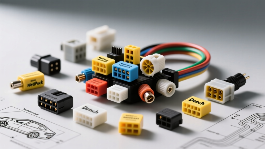
Introduction: Bridging the Gap Between Schematic and Harness
When troubleshooting a parasitic draw or a failed CAN-bus network, the factory wiring diagram is your primary map. However, a schematic only tells half the story. To physically locate, probe, and repair a circuit, you must understand how the diagram's abstract symbols translate into physical auto electrical connector types. Modern vehicles utilize thousands of connection points, ranging from sealed engine bay harnesses to unsealed interior body control modules (BCM). Misidentifying a connector family can lead to damaged terminals, compromised environmental seals, and inevitable corrosion.
In this complete wiring diagram walkthrough, we will decode the nomenclature used in OEM schematics, map them to specific connector architectures, and provide actionable repair data including AWG limits, cavity numbering, and terminal extraction techniques.
Diagram Nomenclature: Identifying Connectors on the Page
Before touching a multimeter, you must interpret the diagram's legend. OEMs use specific alphanumeric codes to denote inline connectors, component pigtails, and ground splices.
- Inline Connectors (e.g., C104, X2, IP-04): Represent harness-to-harness junctions. The 'C' or 'X' prefix usually denotes an inline connection, often found passing through the firewall or kick panels.
- Component Connectors (e.g., PCM C2, Fuel Pump G12): Denote the specific plug mating to a module or sensor. 'C2' refers to the second connector body on the Powertrain Control Module.
- Splice Packs (e.g., SP102, S204): Indicate where multiple wires of the same circuit are joined, often utilizing a sealed crimp sleeve or a specific splice clip connector.
Crucially, diagrams display cavity numbers (e.g., Pin 42, Cavity A3). These numbers correspond to the physical terminal holes on the connector face, which vary wildly depending on the specific auto electrical connector types employed by the manufacturer.
Deep Dive: Delphi/Aptiv Metri-Pack Series
The Metri-Pack family is the undisputed standard for under-hood and under-dash sensor circuits in North American and European vehicles. When your diagram shows a 3-wire MAP sensor or a 4-wire idle air control valve, you are likely looking at a Metri-Pack interface.
Metri-Pack 150 Series
Designed for low-current signal and sensor circuits, the 150 series features a 1.5mm terminal width. In wiring diagrams, these are typically represented by thin signal lines (often 20 AWG or 22 AWG).
- Current Rating: Up to 14 Amps continuous.
- Wire Size: 18 to 22 AWG (0.35mm² to 0.80mm²).
- Seal Type: Individual loose-piece wire seals (cable seals) that must be slipped over the wire before crimping the terminal.
- Diagram Walkthrough Tip: If the schematic shows a 5-volt reference wire (e.g., Light Green/Black) routing to a TPS (Throttle Position Sensor), verify the cavity. Metri-Pack 150 terminals use a delicate primary tang. Probing from the front with a standard test light will bend the tang, ruining the terminal's retention.
Metri-Pack 280 Series
When the diagram shifts to high-current loads like fuel pump relays, cooling fan primaries, or ABS valve solenoids, the 280 series takes over. The terminal width increases to 2.8mm.
- Current Rating: Up to 30 Amps continuous.
- Wire Size: 14 to 18 AWG (1.00mm² to 2.00mm²).
- Pull-to-Seat vs. Push-to-Seat: Older 280 designs are 'pull-to-seat' (the terminal is inserted, then pulled back to lock the secondary plastic retainer). Modern variants are predominantly 'push-to-seat'. Always check the diagram's connector end-view to identify the locking tab orientation.
For a comprehensive breakdown of terminal retention forces and crimp specifications, refer to the Aptiv Connection Systems engineering documentation.
Heavy-Duty & High-Vibration: Weather-Pack and Deutsch DT
When tracing circuits in harsh environments—such as a diesel DEF (Diesel Exhaust Fluid) pump heater circuit or an alternator sense wire routed near the exhaust manifold—diagrams will call out heavily sealed connectors.
Weather-Pack (Packard Electric)
Identifiable by their distinct 'Tower' (male pins) and 'Shroud' (female sockets) housings, Weather-Pack connectors utilize large, cylindrical silicone ribbed seals.
- Terminal Style: Open-barrel crimp with a separate insulation grip and wire grip.
- AWG Compatibility: 14, 16, and 18 AWG.
- Failure Mode: The ribbed seals can degrade under extreme heat cycles, allowing capillary action to wick moisture into the harness. If your diagram shows a high-resistance fault on a heated oxygen sensor ground, inspect the Weather-Pack shroud for brittle, cracked silicone ribs.
Deutsch DT Series
Common in heavy-duty trucks, agricultural equipment, and modern chassis-control modules, the Deutsch DT series uses a solid rear silicone grommet (mat seal) rather than individual wire seals.
- Locking Mechanism: A plastic wedge lock (secondary retention) is inserted into the mating face after the terminals are seated. This prevents terminal back-out under high vibration.
- Current Rating: 13 Amps continuous per cavity.
- Diagram Walkthrough Tip: Deutsch cavities are numbered sequentially on the face (e.g., 1 through 12). When a schematic calls for a CAN-High (Pin 3) and CAN-Low (Pin 11) diagnosis, use a specialized Deutsch extraction tool to depress the rear grommet and release the retention barbs. Never pull the wire.
Connector Specification & Diagram Cross-Reference Table
| Connector Family | Typical Diagram Application | Max Current | Standard AWG Range | Seal Architecture |
|---|---|---|---|---|
| Metri-Pack 150 | 5V Ref, Sensor Signals, Injectors | 14A | 18 - 22 AWG | Loose-piece Cable Seal |
| Metri-Pack 280 | Fuel Pumps, Relays, ABS Solenoids | 30A | 14 - 18 AWG | Loose-piece / Mat Seal |
| Weather-Pack | Older Engine Sensors, Lighting | 20A | 14 - 18 AWG | Cylindrical Ribbed Seal |
| Deutsch DT | Chassis CAN, DEF Pumps, Transmissions | 13A | 16 - 20 AWG | Solid Rear Mat Grommet |
| Superseal 1.2 | Modern ABS, Electronic Throttle Bodies | 14A | 18 - 22 AWG | Integrated Secondary Lock |
Walkthrough Scenario: Tracing a Cooling Fan Circuit
Let us apply this knowledge to a real-world scenario. You are diagnosing a cooling fan that fails to engage on high speed. The wiring diagram shows power routing from the Battery Junction Box (BJB) through a high-current relay, into inline connector C142, and finally to the fan motor ground.
- Locate C142 on the Diagram: The schematic identifies C142 as a 4-cavity inline connector. The high-speed feed is identified as a 10 AWG Red/Yellow wire in Cavity A.
- Identify the Physical Connector: A 10 AWG wire carrying 40+ Amps cannot use a Metri-Pack 150. Under the hood, this is almost certainly a Metri-Pack 630 or a heavy-duty AMP/Tyco MCP (Multi-Contact Point) connector. These feature massive 6.3mm blade terminals.
- Probe Safely: Because MCP and 630-series terminals have deep, shrouded cavities to prevent accidental shorting, standard back-probes will not reach. You must use a specialized long-reach terminal probe or carefully separate the connector halves to measure voltage drop across the male/female interface.
- Check the TPA: High-current connectors utilize a Terminal Position Assurance (TPA) lock—a secondary plastic comb that snaps over the terminals. If the diagram shows intermittent voltage at the fan motor, check if the TPA on C142 is fully seated. A partially seated TPA allows the heavy 10 AWG wire to push the terminal backward during mating, causing an open circuit.
For baseline standards on low-tension automotive cable insulation and temperature ratings referenced in these diagrams, consult the SAE J1128 specification.
Terminal Extraction and Fretting Corrosion
When the diagram points you to a faulty connection, proper extraction is mandatory. Auto electrical connector types utilize different primary and secondary locks.
- Primary Lock: The flexible metal tang (lance) stamped into the terminal itself.
- Secondary Lock: A plastic comb or wedge inserted into the housing.
To extract a Metri-Pack terminal, you must use a hollow-cylinder extraction tool that slides over the wire, enters the front of the cavity, and depresses the metal tangs inward, freeing the terminal to slide out the rear. Prying with a pick will destroy the housing cavity.
A Note on Dielectric Grease: A common myth is that packing a connector with silicone dielectric grease prevents corrosion. In reality, excessive grease can displace the mating contact pressure and increase resistance on low-voltage CAN circuits. For sealed auto electrical connector types, use only a micro-drop of TE Connectivity approved contact lubricant on the terminal tip to prevent fretting corrosion caused by micro-vibrations, while allowing the environmental wire seals to do their job blocking moisture.
Conclusion
Mastering auto electrical connector types transforms a confusing web of lines into a logical, physical roadmap. By cross-referencing the diagram's wire gauge, circuit function, and cavity designations with the physical limitations of Metri-Pack, Weather-Pack, and Deutsch systems, you ensure accurate diagnostics and long-lasting harness repairs.