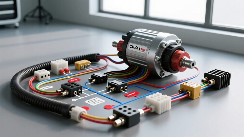
The Philosophy Behind the Charlie's Auto Electric Method
When veteran master technicians refer to the 'Charlie's Auto Electric' method, they are referencing a zero-tolerance, systematic diagnostic philosophy that completely eliminates the modern plague of 'parts-swapping.' Originating from old-school, high-volume auto electric shops where time and accuracy were paramount, this methodology relies on fundamental physics: Ohm's Law, Kirchhoff's Voltage Law, and rigorous under-load voltage drop testing. Instead of immediately condemning a starter motor or an alternator when a vehicle presents a no-crank or parasitic draw complaint, the Charlie's Auto Electric troubleshooting flow forces the technician to verify the electrical architecture from the battery posts to the component pins.
In modern vehicles, a starter circuit is not just a heavy cable and a key switch. It involves the Battery Current Sensor (BCS), the Transmission Range (TR) sensor, the Engine Control Module (ECM), and a network of ISO/Bosch relays. By applying this step-by-step flow, you can isolate high-amperage B+ feeds, 14 AWG control circuits, and alternator exciter loops with surgical precision. Below is the definitive step-by-step troubleshooting flow for starter circuits and charging system parasitic draws, utilizing specific AWG ratings, wire color codes, and connector pinouts.
Phase 1: High-Amperage Ground and B+ Architecture
The most common misdiagnosis in starter circuits is replacing a perfectly functional starter motor that is simply starving for current due to compromised cable architecture. According to Fluke's authoritative guide on voltage drop testing, resistance cannot be accurately measured in high-current automotive circuits using a standard Digital Multimeter (DMM) continuity test. A 2 AWG ground cable with severe internal corrosion may still read 0.01 ohms on the resistance scale, but under a 250-amp starter load, it will choke the circuit.
Step 1: Under-Load Voltage Drop Testing
Set your DMM to the DC millivolt (mV) scale. You will perform two critical tests while an assistant cranks the engine (or while you jump the starter relay).
- Negative Side (Ground) Drop: Place the red probe directly on the negative battery post (not the clamp) and the black probe on a clean, unpainted metal surface on the engine block. Crank the engine. A reading above 100mV (0.1V) indicates excessive resistance. Inspect the main 4 AWG or 2 AWG battery ground cable, the 3/8-inch ring terminal crimps, and the engine-to-chassis ground strap (typically 10 AWG braided copper).
- Positive Side (B+) Drop: Place the red probe on the positive battery post and the black probe on the starter's B+ terminal stud. Crank the engine. A reading above 200mV (0.2V) means the 1/0 AWG or 4 AWG positive cable is failing, or the intermediate junction block (common on GM GMT800 platforms) is corroded.
Expert Note: Always use adhesive-lined, 3:1 shrink ratio marine heat shrink over your crimped ring terminals. Standard vinyl electrical tape will trap moisture, leading to galvanic corrosion between the copper wire and the steel terminal.
Phase 2: Isolating the Starter Control Circuit (S-Terminal)
If the high-amperage architecture passes the voltage drop test but the starter solenoid does not engage, the fault lies in the low-amperage control circuit. This circuit typically utilizes 14 AWG or 16 AWG wire and terminates at the starter's S-terminal (Solenoid trigger).
Step 2: Relay and Neutral Safety Switch Verification
Modern vehicles use a starter relay located in the under-hood fuse box. The ECM grounds the relay coil only when the Transmission Range sensor confirms the vehicle is in Park or Neutral. To troubleshoot this using the Charlie's Auto Electric method, bypass the key switch entirely.
- Locate the starter relay (standard ISO mini-relay). Identify Pin 30 (constant B+ from the battery via a fusible link) and Pin 87 (switched output to the starter S-terminal).
- Using a heavy-duty jumper wire, bridge Pin 30 and Pin 87. If the starter engages, the starter and B+ feed are flawless. The fault is upstream in the control coil circuit (Pins 85 and 86).
- Probe Pin 86 with your DMM (DC Volts). It should show 12V during a crank request. Probe Pin 85; the ECM should provide a switched ground. If Pin 86 lacks voltage, trace the 14 AWG ignition feed (often Yellow or Pink) back through the neutral safety switch.
Vehicle-Specific Wire Colors (S-Terminal Feed):
- GM GMT800 / LS-Swap: 14 AWG Purple wire from the starter relay to the S-terminal. Uses a standard 1/4-inch male spade connector.
- Ford Modular V8 (1997-2008): 14 AWG White/Light Blue or Red/Light Blue wire. Often routed through a fender-mounted solenoid before reaching the starter motor.
- Chrysler HEMI (2005+): 16 AWG Brown/White wire, terminating in a sealed Delphi Weather-Pack 150 series connector at the starter.
Phase 3: The Charlie's Auto Electric Diagnostic Decision Tree
Use this structured decision tree to rapidly isolate starter and cranking system failures without removing components unnecessarily. This aligns with SAE J1739 standards for electrical failure modes and effect analysis.
| Symptom | DMM Measurement | Root Cause | Corrective Action |
|---|---|---|---|
| Single loud 'Click', no crank | B+ Drop > 500mV during crank attempt | Corroded B+ cable or loose 3/8" ring terminal at battery | Cut back cable, re-crimp with hydraulic tool, apply dielectric grease |
| Slow, labored cranking | Ground Drop > 150mV during crank | Engine-to-chassis ground strap broken or corroded at mounting boss | Clean mounting boss to bare metal, replace 10 AWG braided strap |
| Rapid clicking, dash lights dim | Battery drops below 9.6V under load | Bad battery cell or severe parasitic draw draining capacity | Load test battery; proceed to Phase 4 if battery tests good |
| No click, no crank, full dash power | 0V at S-Terminal during crank request | Failed Neutral Safety Switch, bad ECM ground, or open 14 AWG control wire | Jump relay Pins 30/87; if it cranks, diagnose TR sensor alignment |
Phase 4: Alternator Exciter and Parasitic Draw Isolation
A vehicle that cranks perfectly but returns to a dead battery the next morning is suffering from a parasitic draw. The Charlie's Auto Electric method dictates that you never begin pulling fuses blindly. Instead, you isolate the highest-probability architectural flaws first.
Step 3: Testing the Alternator Diode Trio and L-Terminal
The alternator is directly connected to the battery via a heavy 10 AWG or 8 AWG B+ wire. Inside the alternator, a diode trio acts as a one-way check valve, preventing battery current from flowing backward into the stator windings when the engine is off. If a diode shorts out, it will create a massive 1.5A to 3.0A parasitic draw, easily killing a 70Ah battery in 24 hours.
The Isolation Test:
- Set your DMM to the 10A Amperage scale and connect it in series between the negative battery post and the negative cable clamp.
- Wait 20 minutes for the vehicle's CAN-bus modules to enter 'sleep' mode. Acceptable sleep draw is typically under 50mA (0.05A), as noted in Haynes automotive electrical basics.
- If the draw reads 1.5A or higher, locate the main alternator B+ feed at the under-hood fuse box (often a 150A or 175A Mega Fuse).
- Pull the alternator Mega Fuse or disconnect the 10 AWG B+ wire at the alternator's rear terminal (ensure the battery is disconnected first to prevent arcing).
- Reconnect the DMM. If the draw instantly drops to <50mA, the alternator's internal diode trio is shorted. Rebuild or replace the alternator.
Exciter Wire Warning: On older GM CS130 and CS144 alternators, the 'L' (Lamp/Exciter) terminal uses an 18 AWG Brown or Red/White wire. If this wire shorts to ground in the engine harness, it will backfeed through the instrument cluster bulb and create a 0.5A parasitic draw, while also illuminating the battery light on the dash.
Master Reference: Starter & Alternator Circuit Specifications
Keep this specification chart on hand when diagnosing general automotive electrical systems. Adhering to these AWG limits and voltage drop thresholds is the core of the Charlie's Auto Electric methodology.
| Circuit Function | Standard AWG Size | Typical Wire Color (GM/Ford) | Max Allowable Voltage Drop | Common Connector Type |
|---|---|---|---|---|
| Battery to Starter B+ | 1/0 AWG to 4 AWG | Red (Black on GM) | 200mV (0.2V) | 3/8" or 5/16" Ring Terminal |
| Battery to Engine Block Ground | 2 AWG to 4 AWG | Black | 100mV (0.1V) | 3/8" Ring Terminal |
| Starter Relay to S-Terminal | 14 AWG | Purple (GM) / White-Lt.Blue (Ford) | 300mV (0.3V) | 1/4" Spade or Weather-Pack |
| Alternator B+ to Fuse Box | 10 AWG to 8 AWG | Red | 200mV (0.2V) | M8 Ring Terminal / Mega Fuse |
| Alternator L-Terminal (Exciter) | 18 AWG | Brown or Red/White | 500mV (0.5V) | Bosch Junior Timer / Pigtail |
Conclusion
The Charlie's Auto Electric troubleshooting flow is not just a sequence of tests; it is a commitment to electrical integrity. By refusing to guess and instead relying on under-load voltage drop testing, precise relay pin isolation, and systematic parasitic draw elimination, you transform from a parts-replacer into a true diagnostic technician. Whether you are troubleshooting a classic GM 10SI alternator circuit or a modern CAN-bus controlled starter relay network, the physics of voltage, resistance, and current remain unchanged. Respect the architecture, verify the connections, and let the multimeter dictate the repair.