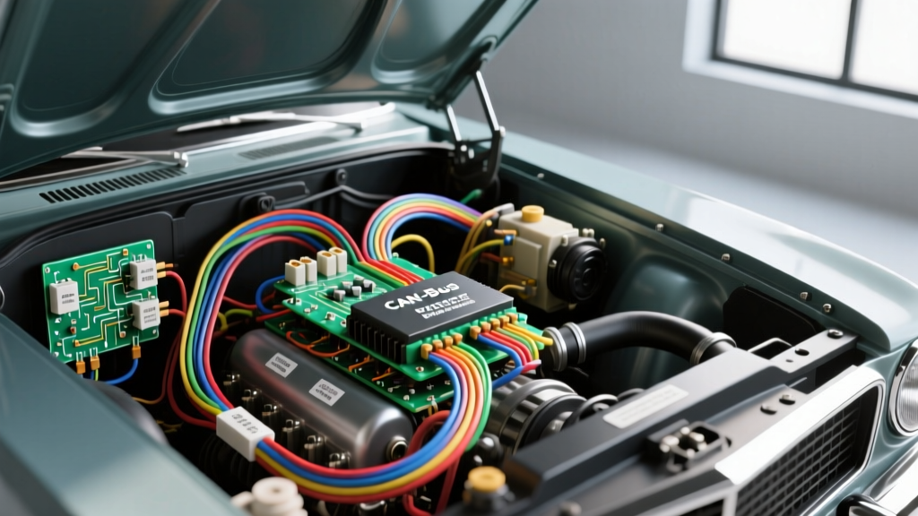
The Shift to Precision Auto Electrics in Restomods
When building a high-performance restomod or a dedicated track car, the electrical system is often the most neglected subsystem. Enthusiasts will spend thousands on forged internals and coilover suspensions, only to rely on a patched-together harness and a 40-year-old glass fuse block. The modern standard for high-end builds is precision auto electrics—a methodology that replaces mechanical relays, blade fuses, and spaghetti wiring with solid-state Power Distribution Modules (PDMs), sealed military-spec connectors, and CAN-bus integrated networks.
Upgrading to a precision auto electrics architecture fundamentally changes how power is distributed and monitored. By utilizing a programmable PDM and a modern high-output alternator, you eliminate voltage drop, reduce harness weight by up to 40%, and gain real-time telemetry for every circuit in the vehicle. This guide details the technical execution of a complete precision electrical overhaul, focusing on PDM integration, alternator sense circuits, and CAN-bus topology.
Core Components: Solid-State PDM and High-Output Alternator
The heart of a precision auto electrics upgrade is the Power Distribution Module. Unlike a traditional fuse box that relies on thermal-magnetic blade fuses and mechanical 30A Bosch-style relays, a PDM uses solid-state MOSFETs to route power. These modules feature programmable current limits, soft-start capabilities to reduce inrush current, and built-in flyback diode protection to prevent voltage spikes from destroying sensitive ECU logic gates.
Pairing a PDM with a modern high-output alternator (such as a 150A Denso-style or Bosch compact unit) requires precise wiring. Classic 10SI alternators relied on a simple dummy light for excitation and regulated voltage based on the alternator's B+ terminal. Modern precision setups require dedicated sense wires and digital regulation to ensure the ECU receives a stable 14.2V, regardless of the draw from fuel pumps and cooling fans.
Wiring the PDM: Pinouts and AWG Specifications
When mapping your PDM, wire gauge selection must be based on the continuous amperage draw of the component, the length of the wire run, and the acceptable voltage drop (kept below 0.2V for power circuits). Below is a specification chart for a typical EFI restomod build utilizing a Motec or Holley PDM.
| Circuit ID | Function | Wire Gauge (AWG) | Max Current | Connector Type | Trigger Logic |
|---|---|---|---|---|---|
| OUT 1 | EFI Fuel Pump | 12 AWG (Stranded) | 15A | Deutsch DT 2-Pin | ECU Pin 42 (12V+ Output) |
| OUT 2 | PWM Cooling Fan | 10 AWG (Stranded) | 30A | Weatherpack 2-Pin | CAN-bus Temp > 205°F |
| OUT 3 | ECU Main Power | 14 AWG (Shielded) | 10A | Metri-Pack 280 | Ignition Switch 'Run' |
| OUT 4 | Injector Bank 1 | 16 AWG (Tefzel) | 8A | Bosch EV14 / USCAR | ECU PWM Signal (Ground) |
| MAIN IN | Battery Feed | 2 AWG (Fine Strand) | 120A | 3/8' Ring Terminal | Direct to Battery + Bus |
Note: Always use MIL-DTL-22520 calibrated ratchet crimpers (such as the M22520/2-01) for terminal crimping. Seal all connections with adhesive-lined polyolefin heat shrink (e.g., 3M FP-301) to prevent micro-corrosion, which is the leading cause of high-resistance faults in precision auto electrics.
Alternator Integration: Sense Wires and Exciter Circuits
A common failure mode in modified vehicles is undercharging at idle or overcharging at high RPM. This is almost always caused by improper alternator sense wiring. In a precision auto electrics build, the alternator's voltage regulator must measure the voltage at the main power distribution bus, not at the alternator's B+ post.
Step-by-Step Alternator Wiring Protocol
- B+ Output Terminal: Route a 4 AWG fine-strand copper cable from the alternator B+ post to a 150A Mega Fuse located within 18 inches of the battery positive terminal. Torque the B+ nut to 10-12 Nm. Do not overtighten, as this will crack the internal rectifier diode housing.
- Sense (S) Terminal: Run an 18 AWG wire from the alternator S-terminal directly to the main PDM power input bus. Install an inline 10A ATO fuse within 6 inches of the bus connection. This wire carries virtually zero current; it only provides a voltage reference to the regulator.
- Exciter/Lamp (L) Terminal: If your custom dash lacks a traditional incandescent charge warning bulb, you must install a 100-ohm, 2-watt pull-up resistor between the L-terminal and a switched 12V ignition source. Without this resistance, the internal voltage regulator will not 'wake up,' resulting in zero alternator output.
- Grounding: Do not rely on the alternator mounting brackets for grounding. Run a dedicated 8 AWG ground wire from the alternator casing ground lug directly to the engine block star-ground point.
CAN-Bus Topology and Shielding Protocols
Integrating your PDM with a modern standalone ECU (such as a Haltech Elite or MoTeC M1) via CAN-bus eliminates dozens of physical trigger wires, further streamlining the harness. However, CAN-bus networks are highly susceptible to Electromagnetic Interference (EMI) from ignition coils and alternator ripple if not wired to SAE J1939 standards.
CAN-Bus Wiring Specifications
- Wire Selection: Use a twisted-pair shielded cable. CAN High (typically Yellow) and CAN Low (typically Green) must be twisted at a rate of 1 to 1.5 twists per inch.
- Termination Resistors: A CAN-bus network requires exactly two 120-ohm termination resistors—one at the ECU end of the bus, and one at the PDM end. Measuring between CAN H and CAN L with a multimeter should yield exactly 60 ohms (two 120-ohm resistors in parallel). If you read 120 ohms, you are missing a terminator; if you read 40 ohms, you have an extra terminator causing signal reflection.
- Shield Drain Wire: The shield's bare drain wire must be grounded at one end only (preferably the ECU ground pin). Grounding both ends creates a ground loop, turning the shield into an antenna that absorbs alternator whine and corrupts data packets.
Real-World Failure Modes in Custom Harnesses
Even with premium components, precision auto electrics systems can fail if foundational installation rules are violated. Use this diagnostic decision tree to troubleshoot common post-build electrical gremlins.
- Symptom: ECU resets when cooling fan engages.
- Cause: High inrush current from the fan motor causing a momentary voltage sag on the main bus, or flyback voltage spike.
- Fix: Verify the PDM soft-start ramp rate is configured to 2.0 seconds for the fan circuit. Ensure the PDM main ground is tied directly to the battery negative, not the chassis.
- Symptom: Alternator whine in audio system / CAN-bus dropouts.
- Cause: Alternator ripple current exceeding 50mV AC due to a poor chassis ground or failing diode trio.
- Fix: Test alternator ripple with a multimeter set to AC Volts. If >50mV, upgrade the engine-to-chassis ground strap to 2 AWG and verify the alternator sense wire is not routed parallel to ignition coil wires.
- Symptom: Intermittent fuel pump cut-out on rough roads.
- Cause: Micro-fretting corrosion inside non-sealed connectors, or a crimp that was compressed with pliers instead of a ratchet crimper.
- Fix: Cut back the wire, strip to bare copper, and re-crimp using sealed Deutsch DT sockets with the proper M22520 ratchet tool. Apply dielectric grease to the socket face before mating.
Authoritative Standards and Best Practices
Executing a precision auto electrics upgrade requires adherence to established automotive and motorsport engineering standards. When designing your harness, refer to the Bosch Automotive Electrics and Electronics guidelines for proper relay suppression and wire derating curves based on under-hood ambient temperatures. Furthermore, consult Painless Performance Products technical manuals for chassis-specific routing strategies that keep wiring away from exhaust headers and moving steering components.
By abandoning legacy fuse blocks in favor of solid-state PDMs, implementing dedicated alternator sense circuits, and strictly following SAE CAN-bus shielding protocols, your build will achieve the reliability and telemetry required for modern high-performance driving. Precision auto electrics is not just about making the engine bay look clean; it is about ensuring that every electron reaches its destination with zero voltage drop and absolute predictability.