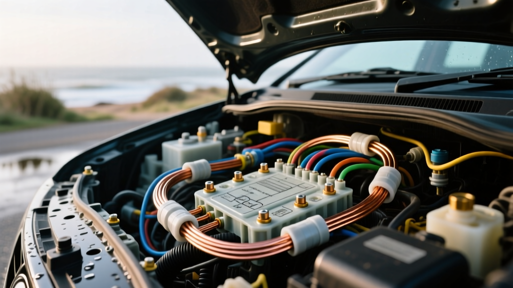
Why Norfolk’s Coastal Climate Demands Marine-Grade Auto Electric Upgrades
Operating a vehicle in or around Norfolk, Virginia, exposes your electrical system to a unique set of environmental stressors. Situated at the mouth of the Chesapeake Bay and adjacent to the Atlantic Ocean, the region's high salinity, heavy humidity, and frequent salt-fog events create an aggressively corrosive environment for standard automotive wiring. When consulting an auto electric Norfolk specialist, the most common failure point identified in older or heavily modified vehicles is galvanic corrosion at the terminal crimps and within the copper strands of standard SAE J1128 primary wire.
Standard bare copper wire oxidizes rapidly in salt-air environments. Once moisture breaches the PVC insulation jacket or wicks through the terminal crimp via capillary action, the copper turns to copper oxide—a poor conductor. This increases resistance, causes severe voltage drop, and ultimately leads to thermal melting of connectors or intermittent module failures. This practical how-to guide details the exact materials, tools, and installation procedures required to upgrade an auxiliary 8 AWG power circuit using marine-grade, coastal-proof auto electrical techniques.
Material Selection: Tinned Copper vs. Bare Copper
To combat coastal corrosion, we must abandon standard automotive wire in favor of marine-specification wire. Marine wire utilizes a proprietary tin coating on every individual copper strand and a more robust insulation jacket (typically cross-linked polyethylene or XLPE) that resists salt, UV, and chemical degradation.
| Specification | Standard SAE J1128 (Auto) | UL 1426 / Marine Grade (Coastal) |
|---|---|---|
| Conductor Material | Bare Copper | Tinned Copper (Type III) |
| 8 AWG Strand Count | 168 strands (0.25mm) | 655 strands (0.10mm) - Ultra-flex |
| Insulation Type | PVC (Thermoplastic) | XLPE (Thermoset, 105°C rated) |
| Capillary Wick Resistance | Poor (moisture travels under PVC) | High (tin coating blocks oxidation wicking) |
Reference: For detailed conductor stranding and insulation standards, refer to the SAE J1128 Low Tension Primary Cable specifications and American Boat and Yacht Council (ABYC) E-11 Standards which are widely adapted for severe-duty automotive applications.
Step-by-Step Installation: Upgrading an 8 AWG Auxiliary Power Circuit
In this scenario, we are installing an 8 AWG marine-grade power feed from the battery to a heavy-duty 120A continuous-duty solenoid in the engine bay, commonly used for winches, auxiliary lighting, or air compressors.
Step 1: Routing and Looming for Salt Protection
Never run marine wire bare through the chassis or firewall. Salt spray accumulation in the wheel wells and lower chassis rails will eventually degrade even XLPE insulation over years of exposure.
- Route the 8 AWG tinned wire away from exhaust manifolds (maintain a minimum 6-inch clearance).
- Encase the wire in split-loom tubing, and wrap the loom in Tesa 51036 PET fleece tape. This prevents the loom from vibrating against the chassis, which can wear through the tape and expose the wire to salt-laden road spray.
- Use Adel clamps (cushion clamps) with a neoprene rubber liner every 12 inches to secure the loom to the chassis. Torque the mounting bolts to 10 Nm to prevent stripping the sheet metal.
Step 2: Stripping and Crimping Adhesive-Lined Terminals
The crimp is the most vulnerable point for coastal corrosion. We will use 8 AWG tinned copper ring terminals with an adhesive-lined heat shrink collar.
- Strip the Wire: Use a precision wire stripper to remove exactly 11mm (7/16") of insulation. Do not nick the tinned strands; a nicked strand creates a stress fracture point that will snap under engine vibration.
- Insert and Crimp: Insert the wire fully into the terminal barrel. Using a ratcheting hex-crimp tool (such as the IWISS IWS-16 or Astro Pneumatic 4508), perform the crimp. The tool must be calibrated to compress the barrel to a hex profile, ensuring a cold-weld gas-tight seal that leaves zero void space for moisture to enter.
- Seal the Joint: Apply heat using a dedicated hot air gun set to 130°C (265°F). Heat the terminal evenly from the middle outward toward the insulation. You will know the seal is complete when the thermoplastic adhesive liner melts and squeezes out slightly at the edge of the insulation jacket, creating a waterproof barrier against salt fog.
Step 3: Dielectric Grease Application
Before attaching the ring terminal to the solenoid stud or battery post, apply a generous layer of Novagard G623 or equivalent silicone dielectric compound. This displaces ambient moisture and prevents galvanic corrosion between the tinned copper terminal and the steel or lead terminal post.
Deutsch DT Connector Pinout and Crimping Specifications
For inline connections in the engine bay or undercarriage, standard plastic Weather-Pack connectors are insufficient for Norfolk's coastal environment. We mandate the use of TE Connectivity Deutsch DT series connectors. These feature a thermoplastic housing with integrated silicone rear seals and secondary wedge locks.
| Component | Part Number | Specification / Note |
|---|---|---|
| Receptacle Housing (2-Pin) | DT04-2P | Grey thermoplastic, IP68 rated when mated |
| Plug Housing (2-Pin) | DT06-2S | Includes integrated silicone grommet seal |
| Solid Pin (Male) | 0462-201-16141 | Nickel-plated copper, Size 16 (14-18 AWG) |
| Socket (Female) | 0460-202-16141 | Nickel-plated copper, Size 16 (14-18 AWG) |
| Wedge Lock (Receptacle) | W2P | Green secondary pin retention lock |
| Wedge Lock (Plug) | W2S | Green secondary pin retention lock |
For official mating cycles, insertion force, and environmental sealing data, consult the TE Connectivity Deutsch DT Series Customer Drawing.
Installation Note: Always crimp the Deutsch contacts using a dedicated open-barrel M22520/2-01 style crimper with the 16-20 AWG selector dial. Insert the crimped contact into the rear of the housing until you feel a distinct 'click' as the internal stainless steel retention fingers grab the contact shoulder. Insert the green wedge lock to permanently secure the pins.
Troubleshooting Coastal Corrosion and Voltage Drop
Even with meticulous installation, coastal vehicles require periodic electrical auditing. Use a high-impedance digital multimeter (DMM) like the Fluke 87V to perform voltage drop tests under load. A healthy 8 AWG marine circuit carrying 40A should exhibit no more than 0.10V drop across the entire length of the wire and terminals.
| Symptom | Probable Cause (Coastal Environment) | Corrective Action |
|---|---|---|
| Auxiliary lights flicker at idle | Micro-corrosion on the alternator sense wire terminal causing voltage regulator hunting. | Clean alternator post with a brass wire brush, re-crimp sense wire with adhesive-lined terminal, apply dielectric grease. |
| Solenoid clicks but fails to engage load | Voltage drop > 2.0V at the ground chassis connection due to salt-induced rust under the grounding ring terminal. | Remove ground bolt, sand chassis to bare metal using 80-grit sandpaper, apply zinc-rich cold galvanizing spray, reinstall with star washer and dielectric paste. |
| Wire insulation feels brittle and cracked | UV and salt-fog degradation of standard PVC wire; thermal cycling from engine heat. | Replace entire run with XLPE marine-grade wire and upgrade to split-loom with PET fleece tape wrapping. |
By adhering to these marine-grade installation protocols, drivers and fleet managers in the Norfolk area can effectively eliminate the hidden costs of salt-air electrical failures, ensuring reliable starting, lighting, and accessory operation year-round.