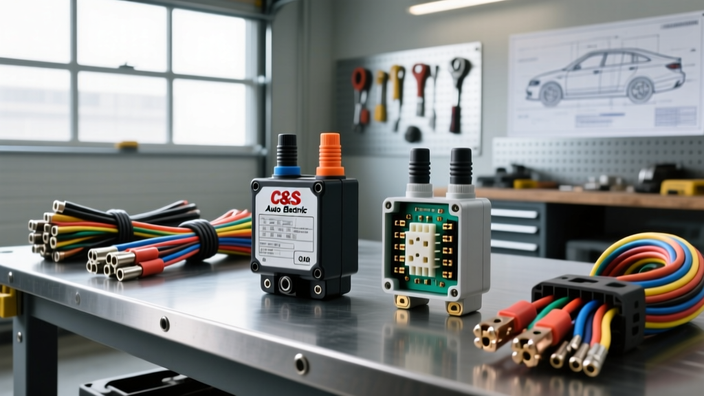
Introduction to High-Amperage Automotive Switching
As modern vehicle electrical architectures evolve to support high-draw accessories like electric AC compressors, dual cooling fan arrays, and 12V winches, standard OEM switching components often fall short. The C&S Auto Electric product line has emerged as a preferred alternative for high-amperage circuits, offering heavy-duty relays, solenoids, and terminal blocks designed to withstand continuous thermal and electrical stress. This guide compares C&S Auto Electric components against standard OEM ISO mini-relays, providing actionable wiring specifications, AWG sizing, and installation protocols for automotive electricians and advanced DIYers.
C&S Auto Electric Heavy-Duty Relays vs. Standard ISO Mini Relays
The most common point of failure in aftermarket high-amp circuits is the use of standard Bosch-style ISO 280 mini-relays (typically rated for 30A/40A intermittent) for loads that exceed their thermal limits. While adequate for headlights or fuel pumps, these standard 5-pin relays suffer from contact welding and coil burnout when subjected to the high inrush currents of electric AC compressors or starter solenoids.
Component Comparison & Specification Chart
| Specification | Standard ISO 280 Mini Relay (OEM) | C&S Auto Electric 80A HD Relay | C&S Auto Electric 200A Contactor |
|---|---|---|---|
| Continuous Amp Rating | 20A - 30A | 80A | 200A |
| Inrush Capacity | 40A (Intermittent) | 120A (Peak) | 800A (Peak) |
| Load Terminal Type | >0.25" Male SpadesM6 / M8 Threaded Studs | 3/8" Threaded Copper Studs | |
| Coil Voltage | 12V DC (70-150 Ohms) | 12V DC (Integrated Suppression) | 12V/24V DC (Dual Coil Options) |
| Best Application | Horns, Fog Lights, Fuel Pumps | Electric AC Compressors, Dual Fans | Winches, Glow Plugs, EV Main Contactors |
Unlike generic relays that rely on simple friction-fit spade terminals, C&S Auto Electric heavy-duty relays utilize M8 (5/16") threaded brass studs for the load circuit. This mechanical fastening eliminates the micro-arcing and subsequent resistance buildup that plagues spade terminals in high-vibration environments. According to SAE J1128 standards for automotive wire and connection integrity, mechanically fastened ring terminals on threaded studs provide superior resistance to thermal cycling compared to push-on spades.
Wiring Harness Selection: Gauge, Terminals, and Color Codes
Selecting the correct C&S Auto Electric component is only half the battle; the wiring harness must be sized to handle the continuous load without exceeding a 3% voltage drop. When wiring a C&S 80A relay for an electric AC compressor, adhere to the following specifications:
Load Circuit (Battery to Relay to Load)
- Wire Gauge: 4 AWG SAE J1128 Cross-Linked Polyethylene (XLPE) for runs under 10 feet. Upgrade to 2 AWG for runs exceeding 15 feet to mitigate voltage drop.
- Wire Color: Red (12V+ Battery Feed), Black (Load to Compressor Ground/Return if applicable, though most compressors ground to chassis).
- Terminals: Non-insulated, heavy-duty copper ring terminals (5/16" / M8 stud size).
- Crimping & Sealing: Use a hydraulic crimper with a 25mm² die. Seal the crimp barrel using dual-wall, adhesive-lined polyolefin heat shrink (3:1 shrink ratio) to prevent moisture ingress and galvanic corrosion.
Trigger Circuit (ECU/Switch to Relay Coil)
- Wire Gauge: 16 AWG or 18 AWG stranded copper.
- Wire Color: Yellow (Switched 12V+ Trigger), White (Coil Ground).
- Connectors: Utilize Bosch-standard Deutsch DT series 2-pin connectors for the coil trigger to ensure IP68 waterproofing in the engine bay.
Real-World Application: Electric AC Compressor Installation
Electric AC compressors (common in EV conversions and modern hybrids) draw significant current. A typical 12V electric compressor can pull 55A continuous with an inrush spike of 90A upon startup. Using a standard 40A relay will result in welded contacts within minutes.
Step-by-Step Wiring Logic
- Main Power Feed: Run 4 AWG Red wire from the battery positive terminal to a 100A ANL fuse holder, then to the C&S 80A Relay's 'BAT' (M8) stud.
- Load Output: Run 4 AWG Red wire from the relay's 'LOAD' (M8) stud directly to the compressor's positive input terminal.
- Torque Specifications: Torque the M8 hex nuts on the C&S relay studs to 8-10 Nm. Under-torquing causes micro-movements and arcing; over-torquing can strip the brass threads.
- Coil Triggering: Connect the ECU's low-side driver (or a manual HVAC switch) to the relay's trigger spades. Pin 85 receives 12V+ from the ignition circuit; Pin 86 connects to the ECU ground trigger.
- Inductive Kickback Protection: If the C&S relay model does not feature an internal flyback diode, you must install a 1N4007 reverse-biased diode across the coil terminals (Stripe to 12V+). When the ECU cuts the ground, the collapsing magnetic field generates a 100V+ spike. Without the diode, this spike will instantly destroy the ECU's low-side driver transistor.
Common Failure Modes and Troubleshooting
Even premium C&S Auto Electric components can fail if the surrounding circuit is poorly designed. Use this diagnostic tree to identify issues in high-amp switching circuits:
Symptom: Relay Clicks, but Compressor Does Not Engage
- Cause 1: Voltage drop across the load contacts. Over time, oxidation on cheap aftermarket relays increases resistance. C&S relays use silver-cadmium oxide contacts to resist this, but improper crimping on the 4 AWG wire can mimic this failure.
- Fix: Perform a live voltage drop test. Place your multimeter probes directly on the relay's input and output M8 studs while the circuit is under load. A reading above 0.1V indicates a poor cable crimp or a failing internal contact. Replace the terminal and re-crimp.
Symptom: ECU Blows Low-Side Driver Upon Relay Deactivation
- Cause: Missing or failed flyback diode. The inductive spike from the relay coil travels back into the ECU.
- Fix: Verify diode orientation. The cathode (silver stripe) must face the 12V+ source, and the anode must face the ECU ground trigger. Test the diode with a multimeter in diode-test mode; it should read ~0.6V in one direction and 'OL' in the reverse.
Symptom: Relay Coil Overheats and Melts the Harness Connector
- Cause: Using a standard 12V relay on a 14.4V+ charging system without adequate coil resistance, or poor ground path resistance causing the coil to pull excess amperage.
- Fix: Measure coil resistance. A healthy 12V C&S relay coil should read between 70 and 150 Ohms. If the resistance is lower, or if the trigger wire (18 AWG) is undersized and heating up, upgrade the trigger wire to 16 AWG and ensure the chassis ground point is sanded to bare metal and treated with dielectric grease.
Conclusion
Upgrading to C&S Auto Electric heavy-duty relays and terminal blocks is a mandatory step for any high-amperage automotive modification. By pairing these robust components with correctly sized SAE J1128 XLPE wiring, adhesive-lined heat shrink, and proper inductive spike suppression, you ensure a reliable, fire-safe electrical architecture capable of handling the demands of modern electric AC compressors and auxiliary systems.