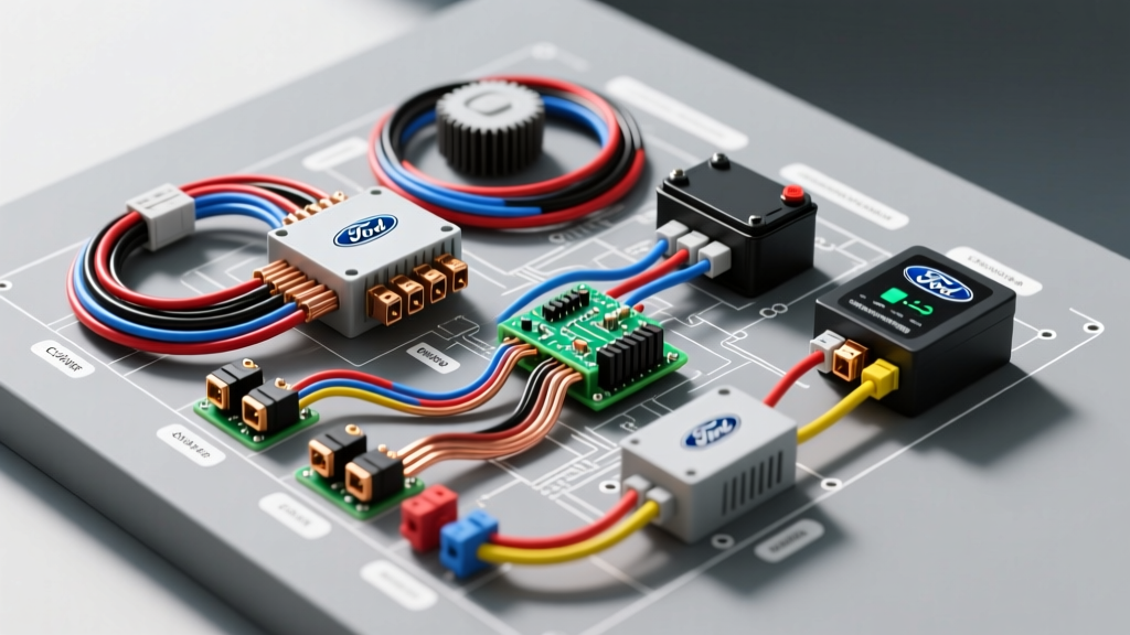
Introduction to the Ford Transit Smart Charging System
Modern commercial vehicles rely on highly sophisticated electrical architectures to manage parasitic draws, optimize fuel economy, and support heavy auxiliary loads. The Ford Transit 3.5L EcoBoost utilizes a Smart Charging System (SCS) that abandons traditional analog voltage regulators in favor of a digital Local Interconnect Network (LIN) bus. When diagnosing complex charging and cranking faults in these vans, the rigorous, climate-aware diagnostic methodology championed by regional specialists like Beaverton Auto Electric provides a masterclass in systematic electrical troubleshooting. In the wet, corrosive environments of the Pacific Northwest, wiring harness degradation is just as common as internal component failure.
This complete wiring diagram walkthrough dissects the Transit's alternator and starter circuits. We will cover exact pin configurations, AWG wire specifications, LIN bus communication protocols, and the Passive Anti-Theft System (PATS) integration required for a successful crank event. Whether you are tracking down a parasitic draw or diagnosing a 'No Charge' condition, this guide provides the OEM-level data necessary to execute precise repairs.
Alternator Wiring Diagram Walkthrough: The LIN Bus Architecture
The Ford Transit uses a 6G-series alternator controlled directly by the Powertrain Control Module (PCM). Unlike older 3-wire systems where the alternator decided its own output based on an internal sense wire, the SCS allows the PCM to request specific voltage targets based on engine load, battery temperature, and accessory demand. This communication happens over a single-wire LIN bus.
According to the SAE J2602 LIN Bus Standard, this network operates at a maximum baud rate of 20 kbps, which is perfectly sufficient for sending simple duty-cycle commands from the PCM to the alternator's internal voltage regulator.
C1023 Alternator Connector Pinout and Wire Specifications
The alternator connects to the vehicle harness via a 3-cavity pigtail connector (Motorcraft WPT-1248). However, only two pins are actively used in the Transit SCS architecture. Below is the exact pinout and wire routing data:
| Pin Cavity | Circuit Function | Wire Color | AWG | Destination / Source |
|---|---|---|---|---|
| 1 | LIN Bus Communication | White/Red (WH/RD) | 18 AWG | PCM Connector C1381, Pin 14 |
| 2 | Not Used (N/C) | - | - | Empty Cavity / Sealed |
| 3 | Generator B+ Sense | Yellow/Black (YE/BK) | 18 AWG | B+ Junction Block (Mega Fuse) |
Backprobing and Oscilloscope Testing the LIN Bus
A common mistake when testing the LIN bus is using a standard digital multimeter (DMM) to check for '12 volts'. Because the LIN bus uses a pulse-width modulated (PWM) square wave, a DMM will only show an averaged, fluctuating voltage (typically between 7V and 11V). To properly verify the circuit, you must backprobe Pin 1 of the C1023 connector with an oscilloscope.
- Key On, Engine Off (KOEO): The PCM sends a 12V square wave to the regulator to wake it up and query its status. You should see a clean 0V to 12V square wave with a 12V dominant high.
- Engine Running: The PCM commands the target voltage. The waveform will shift its duty cycle. A healthy LIN bus will show sharp, clean edges on the square wave. Rounded edges or voltage drops below 10V on the high-side indicate excessive resistance or corrosion in the WH/RD wire—a frequent finding in vans subjected to heavy road salt and moisture.
Starter Motor Circuit and PCM Integration
The starter circuit in the Ford Transit is not a simple key-switch-to-solenoid loop. It is heavily integrated with the PCM and the PATS. When the driver turns the key to 'START', the signal is first routed to the PCM. The PCM then verifies the PATS transponder code. If authorized, the PCM grounds the Starter Relay coil, which in turn sends battery voltage to the starter solenoid.
Starter Relay and Solenoid Routing
The starter relay is located in the Battery Junction Box (BJB) under the hood. The control side of the relay is managed as follows:
- Relay Coil Power (Pin 86): Fed by the Ignition Run/Start circuit (12V).
- Relay Coil Ground (Pin 85): Controlled by the PCM (Pin 22 on C1381). The PCM provides the path to ground only when PATS is satisfied and the transmission is in Park/Neutral (via the TR sensor).
- Relay Switch Feed (Pin 30): Direct B+ from the battery via a 150A Mega Fuse.
- Relay Switch Output (Pin 87): Routes to the starter solenoid 'S' terminal via a 10 AWG Red/Light Blue (RD/LB) wire.
For in-depth relay testing methodologies and voltage drop thresholds, AutoShop 101 Electrical Training provides excellent foundational resources on isolating control vs. load circuit failures.
Real-World Diagnostic Decision Tree
When a Transit rolls into the bay with a charging or cranking complaint, use this structured decision tree to isolate the fault without throwing unnecessary parts at the vehicle. This logical flow mirrors the systematic approach utilized by top-tier diagnostic technicians.
Symptom: Battery Warning Light ON & 'Check Charging System' Message
- Step 1: Perform a static battery test and check the B+ Mega Fuse (150A) in the BJB.
- If Fuse Blown: Check for short to ground on the 4 AWG B+ cable routing to the alternator. Replace fuse and cable.
- If Fuse Intact: Proceed to Step 2.
- Step 2: Measure voltage at the alternator B+ post and the battery positive post simultaneously with the engine running.
- If Voltage Drop > 100mV: High resistance in the B+ cable or terminal corrosion. Clean and retorque.
- If Voltage Drop < 100mV: Proceed to Step 3.
- Step 3: Check the YE/BK sense wire (Pin 3, C1023).
- If Open Circuit: The alternator defaults to a limp-home mode (typically 13.5V) and sets a DTC. Repair the YE/BK wire to the BJB.
- If Sense Wire is Good: Proceed to Step 4.
- Step 4: Scope the WH/RD LIN bus wire (Pin 1).
- If Waveform is Flat at 12V or 0V: PCM is not communicating, or the internal regulator has shorted the bus. Unplug the alternator; if the 12V square wave returns at the harness side, the alternator internal regulator is shorted and the unit must be replaced.
Repair Standards: Combating Corrosion and Ensuring Longevity
Electrical repairs on commercial vans must withstand severe vibration and environmental exposure. When repairing the 18 AWG LIN bus or sense wires, never use twist-and-tape methods. The Motor Data reference standards dictate that all harness repairs must utilize adhesive-lined, dual-wall heat shrink tubing with rosin-core solder connections. This creates a waterproof seal that prevents capillary action from wicking moisture into the copper strands.
Terminal and Fastener Torque Specifications
Improper torque on high-amperage terminals leads to micro-arcing, which generates immense heat and destroys the alternator's rear bearing and internal rectifier. Always adhere to the following specifications during reassembly:
- Alternator B+ Terminal Nut (M8): 10 Nm (89 lb-in). Use a backing wrench on the alternator output stud to prevent twisting the internal rectifier diode pigtails.
- Starter Solenoid 'B+' Nut: 12 Nm (106 lb-in).
- Starter Solenoid 'S' Terminal Nut: 5 Nm (44 lb-in). Over-torquing this small brass nut will strip the threads and compromise the starter relay feed.
- Alternator Mounting Bolts (M10): 48 Nm (35 lb-ft). Ensure the aluminum mounting ears are free of galvanic corrosion to guarantee a solid engine-block ground path.
Summary
Diagnosing the Ford Transit Smart Charging System requires a departure from old-school 'voltage and ground' testing and an embrace of digital network diagnostics. By understanding the LIN bus architecture, verifying the PATS-enabled starter relay circuit, and executing repairs that withstand harsh environmental conditions, technicians can reliably solve complex electrical faults. Whether you are referencing OEM wiring diagrams or applying the rigorous field-tested standards of Beaverton Auto Electric, precision in testing and repair is the ultimate key to mastering modern auto electrical systems.