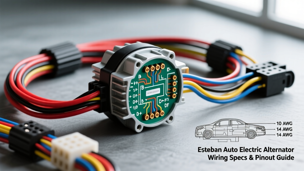
Esteban Auto Electric Component Architecture
When upgrading a vehicle's electrical system to support high-draw accessories like off-road lighting, winches, or aftermarket electric AC compressors, technicians frequently turn to high-output replacement units. Esteban Auto Electric has established a strong reputation in the heavy-duty and light-duty aftermarket for producing robust alternators and voltage regulators. Unlike standard OEM units that rely on complex PCM-controlled LIN (Local Interconnect Network) bus signals, many Esteban Auto Electric high-output alternators utilize traditional analog 1-wire and 3-wire topologies. This makes them ideal for custom chassis wiring, engine swaps, and auxiliary battery isolation systems.
This technical reference outlines the exact pinout configurations, wiring harness specifications, and bench-testing parameters required to properly integrate Esteban Auto Electric alternators into 12V and 24V automotive architectures. Proper execution of these specifications is critical to prevent voltage drop, diode cascade failures, and stator burnout.
Alternator Terminal Pinout Reference
The most common Esteban Auto Electric high-output units utilize a standardized 3-pin or 4-pin regulator connector. Misidentifying the Sense (S) and Ignition (IG) circuits is the leading cause of overcharging and battery boil-off in custom installations. Below is the definitive pinout matrix for the standard Esteban 3-Wire Internal Regulator configuration.
| Pin ID | Terminal Label | Circuit Function | Standard Wire Color | Target Connection Point |
|---|---|---|---|---|
| 1 | B+ (BAT) | Main DC Output | Red (Heavy Gauge) | Starter Solenoid or Battery Positive |
| 2 | L (Lamp) | Charge Indicator / Exciter | Yellow / White Tracer | Dashboard Charge Lamp (via 10-ohm resistor) |
| 3 | S (Sense) | System Voltage Feedback | White / Red Tracer | Direct to Battery Positive (Fused at 10A) |
| 4 | IG (Ignition) | Regulator Wake-Up Signal | Black / Pink Tracer | Ignition Switch 'Run' Position (12V Switched) |
Technical Note on the 'S' (Sense) Terminal: The Sense wire must read the actual voltage at the battery post, not the voltage at the alternator B+ terminal. If the Sense wire is jumpered directly to the B+ post on the back of the Esteban alternator, the regulator will compensate for the voltage drop across the main output cable, resulting in an overcharge condition at the battery (often exceeding 15.2V), which will destroy AGM and Lithium-Iron-Phosphate (LiFePO4) batteries.
AWG Sizing and Voltage Drop Mitigation
Esteban Auto Electric alternators frequently operate in the 150A to 250A continuous output range. Using standard OEM 8 AWG wiring for a 200A unit will result in severe voltage drop, excessive heat generation, and potential harness fires. According to SAE J1128 standards for low-tension primary cable, wire gauge must be selected based on maximum continuous amperage and total circuit length (positive and ground return paths combined).
| Alternator Max Output | Total Cable Length (Round Trip) | Minimum Recommended AWG | Required Ring Terminal Stud Size |
|---|---|---|---|
| 100A - 130A | Under 10 Feet | 4 AWG | 5/16" or 8mm |
| 130A - 170A | 10 to 15 Feet | 2 AWG | 3/8" or 10mm |
| 170A - 220A | 15 to 20 Feet | 1/0 AWG (One-Aught) | 1/2" or 12mm |
| 220A - 280A | Over 20 Feet | 2/0 AWG (Two-Aught) | 1/2" or 12mm |
When crimping 1/0 AWG or larger cables for the B+ terminal, technicians must use a closed-barrel hex crimp tool and apply a layer of marine-grade heat shrink with adhesive lining. Always apply an anti-oxidant compound (such as No-Ox-Id) to the B+ copper ring terminal before torquing it to the alternator output stud to prevent galvanic corrosion and high-resistance hot spots.
Connector and Crimp Specifications
The pigtail connectors used on Esteban Auto Electric units are typically based on the Aptiv (formerly Delphi) Metri-Pack 280 series. These connectors are chosen for their high-current capabilities and robust environmental seals. When repairing or extending a damaged Esteban pigtail, do not use standard open-barrel crimps or solder-only connections, which will fail under engine bay vibration and thermal cycling.
- Terminal Type: Metri-Pack 280 Female, Tin-Plated.
- Wire Seal: Red or Blue silicone ribbed seals (matched to wire insulation OD).
- Crimp Tooling: Use a dedicated Metri-Pack crimp die (e.g., Delphi 12192728 or equivalent) to achieve the correct bellmouth and wire/insulation crimp depth.
- Dielectric Grease: Pack the connector cavity with silicone dielectric grease to prevent moisture ingress and terminal fretting corrosion.
External Regulator Wiring Protocol
For heavy-duty applications requiring precise voltage control (such as running sensitive HAM radios or isolated dual-battery systems), technicians often bypass the internal regulator and utilize an Esteban Auto Electric external solid-state regulator. Wiring an external regulator requires isolating the stator and routing the Field (F) current directly from the regulator.
- Isolate the Internal Regulator: Disconnect the internal brush holder assembly from the stator rectifier bridge. Ensure the original 'F' spade terminal on the case is completely disconnected from the internal circuitry.
- Route the Field Wire: Run a 14 AWG primary wire from the 'F' terminal on the external Esteban regulator to the isolated brush terminal on the alternator. Shield this wire with split-loom tubing to prevent electromagnetic interference (EMI) from the ignition system.
- Connect the Sense and Ignition: Wire the external regulator's 'S' terminal directly to the positive battery post via an inline 15A ATO fuse. Wire the 'IG' terminal to a clean 12V ignition-switched source.
- Grounding: The external regulator case must be grounded to a clean, bare-metal point on the engine block. Do not rely on the mounting bracket alone; run a dedicated 10 AWG ground strap from the regulator base to the block.
Bench Testing Stator and Rotor Assemblies
Before installing a remanufactured or repaired Esteban Auto Electric alternator, perform a bench verification to ensure the internal windings are within specification. According to MotorAlldata diagnostic procedures, testing the rotor and stator prevents immediate failure upon initial engine start.
Rotor (Field) Resistance Test
Set your digital multimeter (DMM) to the Ohms (Ω) setting. Place the probes across the two slip rings on the rotor shaft. A healthy Esteban 12V rotor should read between 2.5 and 4.5 ohms. If the reading is infinite (OL), the internal rotor coil is open. If the reading is below 2.0 ohms, the winding has shorted turns, which will cause the regulator to overwork and fail prematurely.
Stator Continuity and Ground Test
Locate the three stator lead wires where they connect to the rectifier diode trio. Test continuity between each pair of leads (1-2, 2-3, 1-3). The resistance should be virtually zero (typically less than 0.5 ohms). Next, switch the DMM to the highest Megohm range and test from each stator lead to the laminated steel stator core. The reading must be infinite (OL). Any measurable continuity to the core indicates a grounded stator, requiring immediate replacement.
Troubleshooting Voltage Drop and Parasitic Draw
If an Esteban Auto Electric alternator is tested on a bench but fails to charge the battery in the vehicle, the issue is almost always related to harness resistance or a faulty ground return path. Perform a loaded voltage drop test to isolate the fault.
- Positive Side Drop: With the engine running at 1500 RPM and a carbon pile load tester applied to draw 50A, place the DMM positive probe on the alternator B+ post and the negative probe on the battery positive post. A reading higher than 0.2V indicates excessive resistance in the main output cable, connections, or fusible link.
- Ground Side Drop: Place the positive probe on the alternator case and the negative probe on the battery negative post under the same 50A load. A reading higher than 0.1V indicates a poor engine-to-chassis or engine-to-battery ground strap.
- Parasitic Draw Check: Some 1-wire Esteban conversion units utilize an internal excitation circuit that can remain active if the engine is shut off but the ignition switch fails to break the circuit. If a parasitic draw exceeding 50mA is detected at the battery with the key off, install a 12V 40A automotive relay on the B+ output line, triggered by the ignition switch, to physically sever the alternator's connection to the battery when the vehicle is parked.