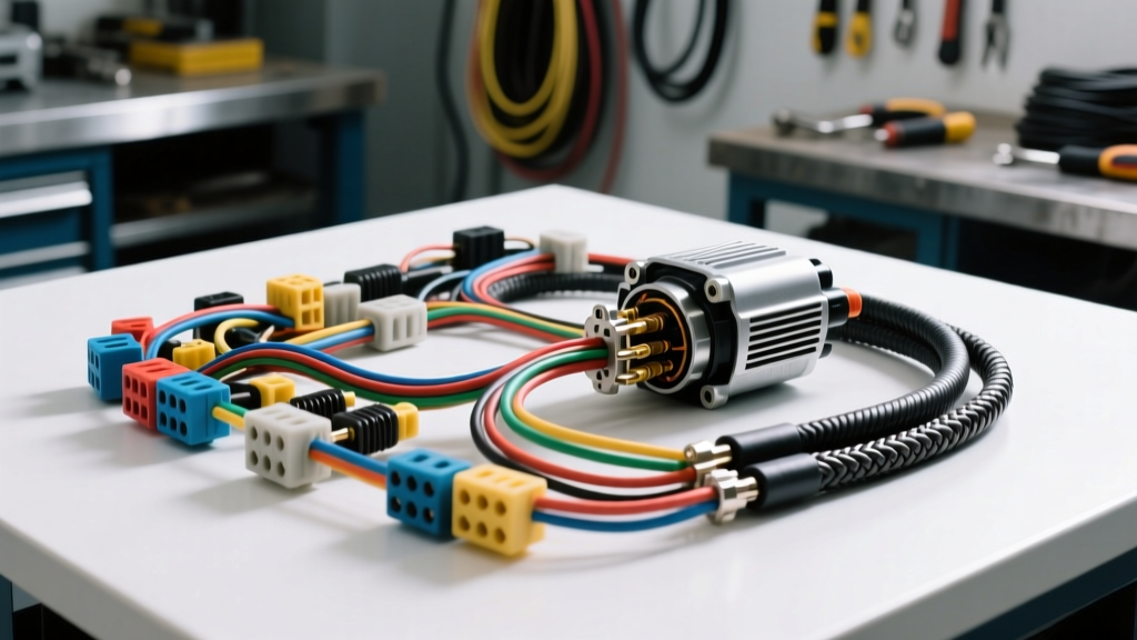
The Gulf Coast Standard: Why Coastal Wiring Demands More
Automotive electrical systems face their ultimate nemesis in coastal environments. High humidity, salt-laden air, and extreme thermal cycling accelerate galvanic corrosion and increase electrical resistance at critical junctions. Veteran repair facilities, notably Hammett's Auto Electric in Biloxi, Mississippi, have built decades of expertise combating these exact failure modes. Their methodology revolves around a core principle: standard OEM wiring harnesses are insufficient for high-amperage, salt-air environments. Upgrading your vehicle's charging and starting circuits requires adopting marine-grade installation practices.
This practical how-to installation guide translates those rugged, Gulf Coast-tested methodologies into a step-by-step blueprint. We will cover the installation of a high-output alternator (such as the 200A Delco Remy AD244), the critical implementation of remote voltage sensing, and the execution of heavy-duty starter circuits using tinned copper and adhesive-lined terminations.
Material Selection: Beating the Salt-Air Corrosion
Standard bare copper wire oxidizes rapidly in humid, coastal climates, leading to a phenomenon known as 'black wire disease' where corrosion wicks beneath the insulation and destroys the conductor from the inside out. To meet the standards expected by experts like Hammett's Auto Electric Biloxi Mississippi, you must upgrade your materials.
- Conductor Type: Use UL 1426 / SAE J378 compliant tinned copper marine wire. The tin coating prevents oxygen and salt from reacting with the copper strands.
- Terminals: Discard open-barrel stampings. Use closed-barrel, heavy-duty ring terminals made of tinned copper.
- Insulation: 3:1 ratio adhesive-lined marine heat shrink. When heated, the inner epoxy lining melts and seals the crimp barrel, creating a watertight barrier that prevents capillary action from drawing moisture into the wire.
- Crimping Tool: Use a hex-indent crimp die, not a standard dot-indenter. Hex crimps deform the barrel evenly around the strands, maximizing surface contact and minimizing voids where corrosion can start.
Table 1: AWG Wire Sizing for High-Output Alternators (Tinned Copper)
Proper gauge selection is critical to prevent voltage drop and thermal runaway. The following chart dictates the minimum AWG size based on alternator output and the total wire run length (alternator B+ to battery positive post).
| Alternator Output | 0 - 7 Feet | 7 - 12 Feet | 12 - 18 Feet |
|---|---|---|---|
| 100A - 140A | 4 AWG | 2 AWG | 1/0 AWG |
| 150A - 200A | 2 AWG | 1/0 AWG | 2/0 AWG |
| 220A - 300A+ | 1/0 AWG | 2/0 AWG | 4/0 AWG |
Source: SAE J378 & ABYC E-11 wiring standards for continuous DC loads.
Step-by-Step: High-Output Alternator & Sense Wire Installation
Upgrading to a 200A alternator requires more than just bolting it to the bracket. The internal voltage regulator must accurately read the battery's state of charge to adjust the field current. If you rely on the alternator's local B+ terminal for sensing, voltage drop across the charge wire will cause the regulator to overcharge the battery, boiling the electrolyte and destroying the cells.
Step 1: Routing the Main B+ Charge Wire
- Disconnect the Battery: Remove the negative terminal first to eliminate ground-fault risks.
- Install the Overcurrent Protection: Install a Class-T or ANL fuse holder within 18 inches of the battery positive post. For a 200A alternator, use a 250A ANL fuse to protect the 2 AWG tinned copper charge wire.
- Route the 2 AWG Charge Wire: Run the wire from the alternator B+ terminal to the battery-side of the ANL fuse. Avoid routing near exhaust manifolds or sharp chassis edges. Use split-loom tubing and P-clamps secured with stainless steel hardware.
- Torque the B+ Terminal: Secure the ring terminal to the alternator B+ stud (typically M8). Torque to 10-12 Nm (89-106 in-lbs). Over-torquing will strip the nut or crack the internal rectifier diode plate.
Step 2: The Critical Remote Sense (S) Wire
The Sense wire is the brain of the charging system. It must read the exact voltage at the battery posts, not at the alternator.
- Cut a length of 10 AWG tinned copper wire.
- Terminate one end with a closed-barrel ring terminal and crimp using a hex die.
- Install an inline 5A AGU or Maxi-Fuse holder within 8 inches of the battery connection point. This protects the sense wire in the event of a short to ground.
- Connect the fused end directly to the positive battery post (under the terminal clamp, not to a secondary accessory block).
- Route the other end to the alternator's 'S' (Sense) pin on the regulator connector. Use a weather-pack seal and a proper Delco extractor tool to seat the pin into the plastic housing until it clicks.
Step 3: Excitation / Ignition (I) Wire
The 'I' terminal wakes up the internal regulator when the ignition is turned on. Connect a 14 AWG wire to a switched 12V+ ignition source. To prevent back-feeding voltage into the dash cluster when the engine is off, install a 1N4001 blocking diode in-line, with the stripe (cathode) facing the alternator.
Heavy-Duty Starter Circuit & Grounding Architecture
A high-output alternator is useless if the starter circuit and grounding architecture suffer from high resistance. Coastal environments destroy factory braided ground straps, leading to voltage seeking alternative paths through throttle cables or heater cores.
- Starter Positive Cable: Replace the factory cable with 1/0 AWG tinned copper. Use a heavy-duty military-spec battery terminal (such as the SAE J1171 standard) that bolts directly to the cable, rather than a lead-pour terminal which is prone to cracking.
- Engine-to-Chassis Ground: Install a minimum 2 AWG tinned ground strap from the engine block (using a clean, bare metal mounting point on the cylinder head) to the chassis rail. Sand away all paint and powder coating to bare metal, apply a coat of dielectric grease after torquing the bolt to 25 Nm to prevent future oxidation.
- Alternator Case Ground: Ensure the alternator mounting brackets are free of corrosion. If using powder-coated brackets, add a dedicated 8 AWG ground pigtail from the alternator casing to the engine block to ensure the regulator has a flawless ground reference.
Voltage Drop Testing & Troubleshooting Matrix
After completing the installation, perform a dynamic voltage drop test. Start the engine, turn on all major electrical loads (headlights, HVAC blower on high, rear defroster), and let the system stabilize at 2000 RPM. Using a digital multimeter (DMM), measure the voltage difference across the connections.
| Symptom / DMM Reading | Probable Cause | Corrective Action |
|---|---|---|
| Battery reads 13.2V, Alternator B+ reads 14.4V (Drop > 0.5V) | Undersized B+ charge wire or corroded ANL fuse contacts. | Upgrade to next AWG size per Table 1; clean fuse terminals with contact cleaner. |
| Battery overcharging (>15.0V) and boiling | Sense (S) wire broken, blown 5A inline fuse, or poor pin seating. | Check continuity of S wire from battery post to regulator pin; replace blown fuse. |
| Starter clicks but won't crank; Voltage drop across ground > 0.2V | Corroded engine block ground strap or paint under terminal. | Remove ground strap, sand to bare metal, re-torque, and apply dielectric grease. |
| Alternator whines; dash lights flicker at idle | Missing or reversed 1N4001 diode on Ignition (I) wire; bad case ground. | Verify diode orientation; install dedicated 8 AWG alternator case ground wire. |
Conclusion
Executing a high-output alternator and starter wiring upgrade requires meticulous attention to material science and circuit architecture. By adopting the marine-grade, anti-corrosion methodologies championed by legacy Gulf Coast shops like Hammett's Auto Electric in Biloxi, Mississippi, you ensure your vehicle's electrical system will deliver reliable, high-amperage performance regardless of the environment. Always adhere to SAE J378 and ABYC E-11 standards for wire sizing and termination, and consult Delco Remy service documentation for specific regulator pinouts and torque specifications.