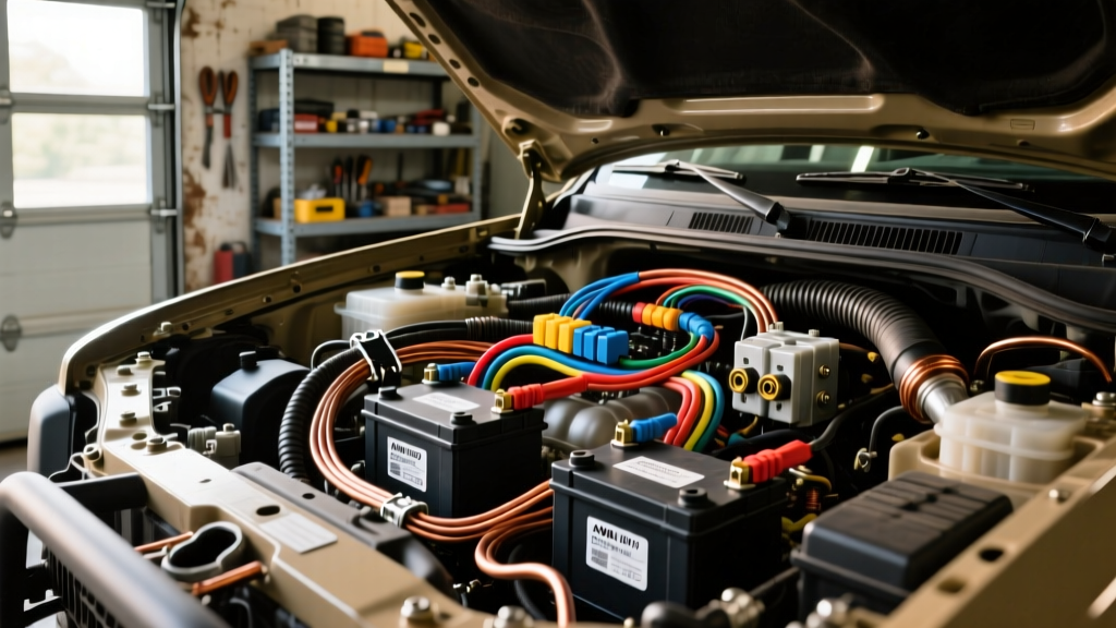
Why Factory Harnesses Fail Under Heavy Accessory Loads
Modern vehicle electrical systems are engineered with precise tolerances, designed to handle the factory ECU, infotainment, lighting, and climate control with a minimal safety margin. When you introduce off-road modifications like 12,000-lb winches, high-output LED light bars, and onboard air compressors, you quickly overwhelm the stock alternator and wiring. Upgrading your vehicle to handle high amps auto electrical accessories requires more than just slapping on a thicker wire; it demands a complete re-evaluation of your power generation, distribution, and grounding architecture.
Stock main power cables are often 4 AWG or 6 AWG aluminum or low-grade copper, rated for 80 to 120 amps. If you install a 250-amp aftermarket alternator but retain the factory B+ cable, the wire becomes a bottleneck, generating excessive heat and causing severe voltage drop. The fundamentals of high amps auto electrical architecture dictate that every connection, from the alternator output stud to the auxiliary distribution bus, must be matched to the maximum potential current of the system.
Calculating Your Total Amperage Draw
Before cutting a single zip tie, you must calculate your continuous and peak amperage requirements. Winches draw massive peak current (often 400+ amps) but only for short bursts. Conversely, auxiliary lighting, cooling fans, and compressors draw continuous current that directly competes with your vehicle's baseline electrical needs.
Off-Road Accessory Amperage Reference Chart
| Accessory Type | Continuous Draw (Amps) | Peak/Surge Draw (Amps) | Minimum Recommended AWG |
|---|---|---|---|
| 12,000-lb Winch | N/A (Intermittent) | 450A - 500A | 1/0 AWG (Battery to Solenoid) |
| 50" LED Light Bar | 22A - 28A | 35A (Inrush) | 10 AWG |
| Heavy-Duty Air Compressor | 30A - 45A | 60A | 8 AWG |
| Dual Electric Cooling Fans | 25A (Combined) | 40A (Startup) | 10 AWG |
| 12V Fridge/Freezer | 5A - 8A | 12A | 12 AWG |
Upgrading the Alternator and Main B+ Cables
To support high-draw modifications, upgrading to a high-output alternator (such as a 250A Denso or Powermaster unit) is usually mandatory. However, the alternator is only as good as the cable carrying its output to the battery and distribution blocks.
Wire Material: OFC vs. CCA
Never use Copper Clad Aluminum (CCA) wire for high amps auto electrical projects. CCA is brittle, has higher resistance, and oxidizes rapidly under the hood's heat cycles. Always specify Oxygen-Free Copper (OFC) or tinned marine-grade copper. Tinned copper resists corrosion and maintains conductivity in harsh, wet, and muddy off-road environments. According to SAE J1128 standards for low-tension primary cables, stranded OFC wire provides the necessary flexibility to route through the firewall and engine bay without fracturing from engine vibration.
For a 250-amp alternator upgrade, the main B+ positive cable must be upgraded to 1/0 AWG OFC. The factory alternator B+ terminal nut typically requires a torque specification of 10 to 12 Nm (89 to 106 in-lbs). Over-torquing can strip the brass stud, while under-torquing creates a high-resistance micro-gap that will melt the terminal under load.
Installing a Continuous Duty Solenoid Isolator
When adding a secondary battery for winching and camp accessories, you must isolate it from the starting battery to prevent draining your cranking reserve. While solid-state relays are common, a heavy-duty continuous duty solenoid (such as the Cole Hersee 24059 or Blue Sea Systems 7610) remains the gold standard for rugged off-road builds due to its mechanical reliability and high surge tolerance.
Step-by-Step Solenoid Isolator Wiring
- Mounting: Secure the solenoid to the firewall or inner fender well using stainless steel hardware. Ensure the mounting bracket is grounded if the solenoid case requires it (check manufacturer specs).
- Main Power Terminals: Connect the primary positive from the starting battery to one large copper stud (typically marked 'BAT' or 'IN'). Connect the secondary positive from the auxiliary battery to the opposite stud ('AUX' or 'OUT'). Use 2/0 AWG red OFC wire for these main runs.
- Ignition Trigger Circuit: The small ignition terminal (often labeled 'I' or 'IGN') requires a 12V switched signal. Tap into an ignition-switched fuse in the cabin using an add-a-circuit fuse tap. Run 14 AWG red wire through the firewall grommet to the trigger post.
- Grounding the Coil: If your solenoid requires an external ground for the internal coil, connect a 14 AWG black wire from the 'GND' post to a clean, bare-metal chassis ground point.
- Fusing: Install a 250-amp Class T fuse on the positive cable within 7 inches of the starting battery terminal, and another on the auxiliary battery side. This protects the main harness in the event of a catastrophic dead short.
Fusing Standards and Terminal Crimping
The most common point of failure in aftermarket high amps auto electrical systems is poorly crimped terminals. Hammer crimpers and pliers deform the copper strands unevenly, creating air pockets that invite corrosion and increase resistance. For 4 AWG and larger wires, you must use a hydraulic or ratcheting hex-crimp tool. The hex crimp compresses the copper strands uniformly, creating a cold-weld effect that is impervious to vibration.
After crimping, seal the connection using 3:1 ratio adhesive-lined heat shrink. The inner thermoplastic adhesive melts and flows into the wire strands, creating a waterproof barrier that prevents capillary wicking of moisture into the cable.
Heavy-Duty Fuse Selection Guide
| Wire Gauge (AWG) | Max Continuous Ampacity | Recommended Fuse Class | Application |
|---|---|---|---|
| 4/0 AWG | 600A | Class T (300A-500A) | Battery Bank Main Disconnect |
| 1/0 AWG | 300A | ANL or Class T | High-Output Alternator B+ Run |
| 2 AWG | 225A | MEGA / AMG | Primary Distribution Busbar |
| 4 AWG | 150A | MEGA or MIDI | Winch Solenoid Power Feed |
| 8 AWG | 80A | MAXI or Circuit Breaker | Air Compressor / Lighting Relays |
For detailed specifications on automotive fuse interrupt ratings and time-current curves, refer to the Littelfuse Automotive Fuse Catalog. Selecting a fuse with the correct interrupt rating (AIC) is critical; a standard glass AGC fuse will explode if subjected to a 500-amp dead short from a lithium or high-CCA AGM battery.
Troubleshooting Voltage Drop in Upgraded Systems
Even with oversized wiring, off-road vehicles frequently suffer from voltage drop due to poor grounding practices. The ground circuit is just as critical as the positive feed. A fundamental rule of high amps auto electrical design is that the ground wire must be equal in gauge to the positive wire for any dedicated accessory run back to the battery or main busbar.
If your winch bogs down or your LED lights flicker at idle, perform a voltage drop test using a digital multimeter. Set the meter to DC Volts. Place the red probe on the alternator B+ terminal and the black probe on the positive battery post while the engine is running and under load (e.g., winching or with all lights on). A reading above 0.2V indicates excessive resistance in the positive cable or a failing crimp terminal. Repeat the test on the ground side (alternator case to battery negative). If the voltage drop is high, remove the ground ring terminal, sand the chassis paint down to bare steel using 80-grit sandpaper, apply a star washer to bite into the metal, torque to spec, and coat the finished connection with dielectric grease to prevent galvanic corrosion.
By adhering to these rigorous wiring standards, utilizing proper OFC cabling, and implementing robust fusing strategies, your modified vehicle will reliably handle the extreme electrical demands of the trail without leaving you stranded in the dark. For further reading on heavy-duty DC wiring standards, the ABYC E-11 Electrical Standard provides exceptional guidelines for 12V high-amperage environments that translate perfectly to overland and off-road automotive builds.