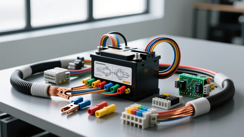
Understanding the 'Hot Wire' in Automotive Architecture
In automotive electrical terminology, a 'hot wire' refers to any circuit carrying constant, unswitched battery voltage (B+). These main power feeds route directly from the battery positive terminal to the main fuse box, alternator, or high-amperage distribution blocks. When performing a hot wire auto electric repair, you are dealing with the most critical and potentially dangerous circuits in the vehicle. Unlike switched ignition circuits that carry minimal current, main B+ feeds can transmit upwards of 150 to 300 amps. A poorly executed repair on a constant 12V feed can lead to catastrophic voltage drops, melted insulation, or severe electrical fires.
This comprehensive guide details the professional methodology for safely diagnosing, cutting, crimping, and routing high-amperage hot wires, specifically focusing on 8 AWG to 2/0 AWG main battery feeds.
Critical Safety Protocols for Live Circuit Repairs
Before touching any constant 12V wiring, strict safety protocols must be followed to prevent arc flashes and short circuits.
- Isolate the Ground: Always disconnect the negative (-) battery terminal first. This eliminates the risk of your tools shorting the B+ feed to the chassis ground while working.
- Capacitor Discharge: Modern vehicles contain high-capacity capacitors in the ECU, airbag modules, and infotainment systems. Wait a minimum of 5 minutes after disconnecting the battery before cutting into any main harness.
- Eye Protection: High-strand copper wire can snap and pierce the skin or eyes when under tension or when a crimp fails. Always wear ANSI-rated safety glasses.
Step-by-Step Hot Wire Auto Electric Repair Guide
Step 1: Tracing and Isolating the Damaged B+ Feed
Identify the exact path of the damaged hot wire. Main B+ feeds are typically routed along the chassis frame rail or through the engine bay firewall. Inspect the entire length of the wire for chafing, melted loom, or green copper oxide corrosion. If the damage is localized near the battery terminal, you may only need to replace the terminal end. If the damage extends into the main harness, a complete section must be excised and replaced.
Step 2: Selecting the Correct Wire Gauge and Insulation
Never use standard PVC-insulated wire for under-hood B+ feeds. According to SAE J1128 standards, you must use cross-linked polyethylene (XLPE) insulated wire, specifically GXL (thin-wall) or SXL (standard-wall). GXL wire is rated for continuous under-hood temperatures up to 125°C (257°F) and offers superior resistance to battery acid, oil, and abrasion compared to standard THHN or PVC wires.
Step 3: Precision Stripping and Preparation
When stripping 8 AWG or larger wire, avoid using standard plier-type strippers that can nick the copper strands. Nicked strands create localized resistance points that generate excessive heat under high loads. Use a precision wheel-type wire stripper or a dedicated heavy-duty gauge stripper. Strip exactly the length required for the closed-barrel terminal—usually 5/8 of an inch for standard 8 AWG ring terminals. The copper strands must remain perfectly intact and unbunched.
Step 4: Executing the Closed-Barrel Hex Crimp
The most common failure point in amateur hot wire auto electric repair is the use of open-barrel or indent crimps on high-amperage circuits. For any wire larger than 10 AWG carrying constant B+ voltage, you must use a closed-barrel hex crimp.
- Slide a piece of 3:1 adhesive-lined dual-wall heat shrink over the wire before crimping.
- Insert the stripped wire fully into the tinned copper closed-barrel terminal until it bottoms out.
- Use a hydraulic hex crimper with the correct die size (e.g., an 8 AWG die for 8 AWG wire and terminal). The hex crimp compresses the barrel uniformly, creating a gas-tight, cold-weld bond that prevents oxygen and moisture from entering the joint.
- Perform a pull-test. Per Delphi Automotive Connection Systems specifications, a properly crimped 8 AWG terminal should withstand a minimum pull-out force of 120 lbs without the wire slipping.
Step 5: Sealing and Torque Specifications
Once crimped, slide the adhesive-lined heat shrink over the barrel and the wire insulation. Apply heat evenly using a heat gun set to 250°C. The polyamide adhesive inside the shrink will melt and extrude slightly from the ends, creating a 100% waterproof seal against galvanic corrosion. When attaching the ring terminal to the battery post or distribution block, use a torque wrench. For a standard M8 battery terminal nut, the factory torque specification is typically 10 to 12 Nm (89 to 106 in-lbs). Overtightening will stretch the bolt and crack the terminal; undertightening will cause arcing and thermal runaway.
Wire Gauge and Ampacity Reference Chart
When replacing a damaged hot wire, always match or exceed the original equipment manufacturer (OEM) gauge. The chart below outlines the maximum continuous current ratings for GXL chassis wiring in high-temperature engine bay environments, paired with the appropriate Littelfuse MEGA or AMG fuse ratings.
| Wire Gauge (AWG) | Max Continuous Amps (Engine Bay) | Recommended MEGA/AMG Fuse | Typical Application |
|---|---|---|---|
| 8 AWG | 40A - 50A | 50A - 60A | Audio amplifiers, auxiliary fuse blocks |
| 6 AWG | 60A - 75A | 70A - 80A | Electric cooling fans, winch control feeds |
| 4 AWG | 85A - 100A | 100A - 125A | Alternator B+ feeds (standard output) |
| 2 AWG | 120A - 130A | 150A | High-output alternator feeds, starter feeds |
| 1/0 AWG | 170A - 190A | 200A - 225A | Main battery to starter motor, EV high-current |
| 2/0 AWG | 210A - 240A | 250A - 300A | Heavy duty diesel main chassis grounds/feeds |
Troubleshooting Common Failure Modes in Main B+ Feeds
Even after a repair is completed, validation is required to ensure the hot wire auto electric repair will withstand the vehicle's operational demands. Use a digital multimeter (DMM) set to millivolts (mV) DC to perform a voltage drop test across the repaired connections.
1. Excessive Voltage Drop
Symptom: The vehicle cranks slowly, or the alternator fails to charge above 13.8V at the battery.
Cause: A poor crimp connection or undersized wire gauge. According to SAE J1211 standards, a single connection point (such as a crimped terminal) should exhibit a voltage drop of no more than 10mV (0.010V) under load. A total cable run should not exceed 100mV to 200mV depending on the circuit.
Fix: Re-crimp the terminal using the correct hex die. Ensure no copper strands were folded back during insertion, which reduces the effective cross-sectional area of the wire.
2. Galvanic Corrosion Under the Insulation
Symptom: The wire feels stiff near the terminal, and a green/white crust forms at the heat shrink boundary.
Cause: Moisture ingress due to the use of single-wall heat shrink or non-adhesive electrical tape. Battery acid vapors in the engine bay accelerate this corrosion, turning the copper into a non-conductive copper oxide.
Fix: Cut back the wire past the visible corrosion (copper must be bright and shiny). Re-crimp using a new terminal and seal exclusively with 3:1 dual-wall adhesive heat shrink.
3. Thermal Melt at the Fuse Holder
Symptom: The plastic housing of the MEGA fuse block is warped or discolored brown/black.
Cause: The MEGA fuse bolts were not torqued to spec, causing micro-arcing and extreme localized heat, or the wire gauge is too small for the continuous load, causing the entire wire to act as a resistor.
Fix: Replace the warped fuse holder. Verify the wire gauge against the ampacity chart above. Torque the MEGA fuse mounting nuts to 12 Nm to ensure maximum surface contact area.
Final Routing and Loom Protection
A successful hot wire repair is not complete until the wire is properly secured. Route the new B+ feed away from high-heat sources such as exhaust manifolds and turbochargers. Maintain a minimum clearance of 6 inches from exhaust components unless a high-temp silicone or fiberglass fire sleeve is used. Secure the wire every 8 to 12 inches using UV-resistant nylon cable ties or OEM-style push-pins. Finally, encase the wire in a split corrugated loom and wrap the loom in Tesa-style fleece automotive harness tape to prevent abrasion against the chassis and eliminate rattling noises. By adhering to these strict OEM-level procedures, your hot wire auto electric repair will provide safe, reliable power delivery for the life of the vehicle.