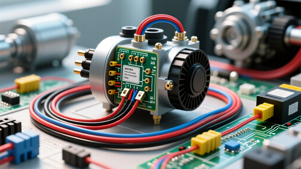
Introduction to Car Electric Aircon Architecture
The modern car electric aircon system represents a fundamental shift in automotive thermal management. Unlike traditional swashplate or scroll compressors driven by the engine's serpentine belt, electric AC compressors (e-A/C) feature an integrated high-voltage (HV) inverter and a 3-phase AC motor. This architecture allows the HVAC system to maintain cabin cooling and battery thermal management even when the internal combustion engine is off, a critical requirement for hybrid electric vehicles (HEVs), plug-in hybrids (PHEVs), and battery electric vehicles (BEVs).
As an automotive electrical technician, diagnosing a car electric aircon system requires a dual-discipline approach. You must simultaneously evaluate the high-voltage DC power supply, the 3-phase internal motor windings, and the low-voltage (LV) data communication networks. This technical specification reference details the wiring architectures, AWG sizing requirements, pinout configurations, and dielectric safety protocols necessary for servicing OEM e-A/C compressors, with a specific focus on industry-standard Denso and Sanden units.
High-Voltage Power Circuit Specifications
The primary power source for a car electric aircon compressor is the vehicle's high-voltage traction battery, routed through the Power Distribution Unit (PDU) or High-Voltage Junction Box (HVJB). The compressor's internal inverter requires a stable DC input, typically ranging from 200V to 400V in standard hybrid platforms, and up to 800V in modern 800V-architecture BEVs. The internal inverter then rectifies this DC voltage into a high-frequency, 3-phase AC waveform to drive the internal scroll motor.
AWG Sizing and Shielding Requirements
Because the compressor is a high-draw inductive load, proper cable sizing and electromagnetic interference (EMI) shielding are non-negotiable. Peak current draw during compressor startup (locked rotor amperage equivalent) can exceed 40A, while continuous cruising draw typically settles between 8A and 15A.
- Cable Gauge: 8 AWG (approx. 10mm²) stranded copper is the OEM standard for circuits up to 3kW. For high-capacity rear HVAC units or 800V systems requiring thicker insulation, 6 AWG may be utilized.
- Jacket Color: All HV cabling must be encased in an orange PVC or cross-linked polyethylene (XLPE) jacket to denote shock hazard, per SAE J2929 safety standards.
- EMI Shielding: The 3-phase switching of the internal inverter generates severe EMI. HV cables must feature a braided copper shield. Crucially, this shield must be grounded at the PDU source using a 360-degree shield ring, but left floating at the compressor connector to prevent high-frequency ground loops that can corrupt LV CAN-bus signals.
High-Voltage Interlock Loop (HVIL) Integration
The HV connector on the compressor is typically a 2-pin or 3-pin sealed Amphenol or Deutsch receptacle. If a 3-pin connector is used, the third circuit is dedicated to the HVIL. The HVIL is a low-voltage (usually 5V or 12V) continuity loop that passes through the mating connector. If the HV plug is unseated or the connector lock is broken, the HVIL circuit opens, prompting the Battery Management System (BMS) to instantly open the main contactors, de-energizing the compressor before the HV pins physically separate.
Low-Voltage Control and LIN Bus Pinouts
While the HV circuit provides the muscle, the LV circuit provides the brain. The HVAC control module dictates compressor speed (RPM) and displacement via a digital data bus. Most modern OEMs utilize the Local Interconnect Network (LIN) bus due to its low cost and sufficient bandwidth for single-node actuator control, though some advanced thermal management systems integrate the compressor directly onto the high-speed CAN-bus.
Below is the standard 4-pin LV control connector pinout reference for a typical Denso car electric aircon compressor (using a Sumitomo TS 025 4-way sealed connector):
| Pin # | Wire Color (OEM Std) | AWG | Function / Signal Type | Electrical Characteristics |
|---|---|---|---|---|
| 1 | Red / White Stripe | 18 AWG | 12V Constant Battery (B+) | Supplies power to the LV logic board and LIN transceiver. Fused at 10A. |
| 2 | Purple / White | 20 AWG | LIN Bus Data | 12V square wave, 19.2 kbps. Carries RPM commands and fault codes. |
| 3 | Black | 18 AWG | Signal Ground (SGND) | Clean logic ground. Must not be shared with HV chassis ground. |
| 4 | Yellow | 20 AWG | Enable / Wake (IGN) | 12V switched. Wakes the inverter logic from sleep mode. |
Diagnostic Note: When probing Pin 2 (LIN Bus) with an oscilloscope, a healthy idle signal will show a 12V dominant-high square wave with distinct data frames dropping to near 0V. If the line is pulled flat to 12V or 0V, the LIN transceiver inside the compressor or the HVAC master node has failed.
Dielectric Refrigerant Oil Specifications
One of the most catastrophic mistakes a technician can make when servicing a car electric aircon system is using standard Polyalkylene Glycol (PAG) oil. PAG oil is highly hygroscopic (absorbs moisture) and becomes electrically conductive when exposed to ambient humidity. Because the 3-phase motor windings in an e-A/C compressor are bathed directly in the refrigerant/oil mixture, conductive oil will cause a short circuit between the HV windings and the aluminum compressor housing.
Electric compressors strictly require Polyolester (POE) oil or OEM-specific dielectric formulations like Denso ND-OIL 11. These oils possess a high dielectric breakdown voltage (typically >30kV) and low moisture absorption rates. Mixing even 5% PAG oil into an e-A/C system can lower the dielectric strength enough to trigger an internal insulation fault, permanently destroying the inverter.
Troubleshooting Decision Tree: Inverter and ISOH Faults
When a car electric aircon compressor fails to engage, the HVAC module will often log an Isolation High/Low (ISOH) or Insulation Resistance fault. This indicates that the inverter has detected a current leak to the chassis ground. Follow this diagnostic sequence:
Step 1: Verify LV Communication and Wake Signals
Before condemning the HV system, ensure the logic board is awake. Check Pin 1 for 12V constant and Pin 4 for 12V switched IGN. If the LV logic is dead, the inverter cannot close its internal HV contactors, and the compressor will remain silent. Check the 10A HVAC fuse in the engine bay fuse box.
Step 2: Perform a Megger Test on HV Windings
WARNING: Never use a standard digital multimeter (DMM) to test HV insulation. A DMM's 9V battery cannot detect microscopic dielectric breakdowns under load. You must use a dedicated insulation resistance tester (Megger) set to 500V DC.
- Disconnect the HV orange cable from the compressor.
- Ensure the LV 12V connector is also disconnected to prevent back-feeding and frying the logic board.
- Connect the Megger positive lead to the compressor HV terminal and the negative lead to the bare aluminum compressor housing.
- Apply 500V DC. A healthy compressor will read >50 Megaohms. A reading below 5 Megaohms indicates internal winding insulation failure or conductive oil contamination.
Step 3: Inspect the HV Connector and Shield Ground
If the Megger test passes, the fault may lie in the external wiring. Inspect the orange HV cable for pinch points where the EMI shield might be contacting the vehicle chassis. A grounded shield will immediately trigger an ISOH fault upon inverter startup. Additionally, check the HV connector terminals for micro-arcing or green copper oxide corrosion, which can create a high-resistance path to ground.
Authoritative References and Further Reading
The specifications and safety protocols outlined in this guide are derived from established automotive electrical engineering standards and OEM service documentation. For deeper exploration into high-voltage safety and e-A/C architecture, consult the following resources:
- SAE International J2929 - Safety Standard for Electric and Hybrid Vehicle High Voltage Systems. This document dictates the physical routing, shielding, and interlock requirements for all HV cables, including those powering the electric aircon compressor.
- Denso Global Thermal Systems - Technical service bulletins and specification sheets for ND-OIL 11 dielectric refrigerant oil and LIN-bus communication protocols for Denso e-A/C units.
- National Highway Traffic Safety Administration (NHTSA) - EV and Hybrid high-voltage system safety guidelines, emergency response guides, and insulation resistance testing protocols for first responders and certified technicians.
Proper diagnosis of a car electric aircon system bridges the gap between traditional HVAC mechanics and advanced power electronics. By strictly adhering to AWG sizing, utilizing proper dielectric fluids, and employing high-voltage insulation testing, technicians can safely and accurately restore critical thermal management systems in modern electrified vehicles.