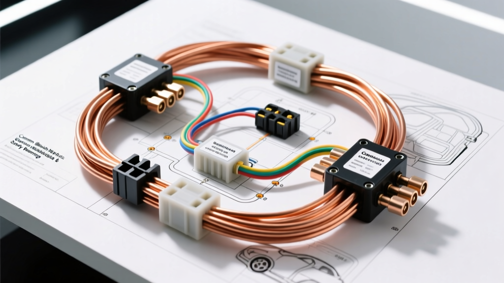
The Midwest Climate Factor: Why Illinois Auto Electric Repairs Fail
When veteran technicians discuss illinois auto electric repairs, they are usually referring to a very specific set of environmental challenges. The Midwest corridor is notorious for extreme temperature swings, ranging from -20°F wind chills in January to 100°F humidity in July. Furthermore, the aggressive use of calcium chloride and rock salt on interstate highways creates a highly corrosive environment for automotive wiring harnesses. A hallmark of illinois auto electric diagnostics is finding catastrophic harness failures that simply do not occur in warmer, drier climates. Whether you are a DIY enthusiast tackling a snow plow installation or a professional diagnosing a parasitic battery draw, avoiding common wiring mistakes is critical for vehicle safety and reliability.
Mistake #1: Relying on PVC Electrical Tape in High-Salt Environments
One of the most frequent errors seen in aftermarket auto electrical work is the use of standard PVC electrical tape to seal wire splices. While high-quality tape like 3M Super 33+ is excellent for bundling and harness wrapping, it is entirely inadequate for sealing a splice in a 14 AWG blower motor wire or a 16 AWG sensor circuit exposed to the elements.
The Adhesive-Lined Heat Shrink Standard
In high-salt environments, capillary action will draw saltwater directly into the crimp barrel of a standard butt connector, leading to rapid galvanic corrosion and increased resistance. Professional illinois auto electric shops exclusively use adhesive-lined polyolefin heat shrink (often referred to as dual-wall heat shrink). When heated, the inner layer of hot-melt adhesive melts and flows around the wire strands and the connector barrel, creating a 100% waterproof seal. For standard 16-14 AWG automotive wire, a 3/16-inch or 1/4-inch dual-wall heat shrink tube should be used, applying heat evenly until the adhesive extrudes slightly from both ends.
Mistake #2: Chassis Ground Neglect and Galvanic Corrosion
A poor ground is the root cause of over 60% of all automotive electrical gremlins. In rust-belt states, chassis ground points are highly susceptible to corrosion. A common mistake is grounding an aftermarket accessory (like a CB radio or auxiliary light bar) to a painted surface or using a standard flat washer that fails to bite through the factory e-coat.
Proper Grounding Protocols
- Surface Preparation: Always use a wire brush or sanding disc to remove paint, powder coating, and rust down to bare, shiny metal at the grounding point (e.g., GM ground G203 behind the passenger kick panel or Ford G101 in the engine bay).
- Hardware Selection: Never use standard steel bolts, which will rust and expand, cracking the ground lug. Use zinc-plated or brass hardware.
- Star Washers: Always place an internal-tooth star lock washer between the wire ring terminal and the bare metal chassis to ensure vibration resistance and a gas-tight connection.
- Corrosion Inhibition: After torquing the ground bolt, coat the entire terminal in dielectric grease or a dedicated electrical contact inhibitor to block moisture and road salt.
Mistake #3: The 'Upsize the Fuse' Blower Motor Fallacy
During the dead of winter, a failing HVAC blower motor will begin to draw excessive amperage due to worn internal bushings or debris in the squirrel cage. If a factory 15A fuse blows repeatedly, a dangerous and common DIY mistake is to replace it with a 20A or 25A fuse to 'keep the heat running.'
This is a severe fire hazard. According to the SAE J1128 Low Tension Primary Cable Standard, standard automotive primary wire (16 AWG to 14 AWG) has specific ampacity limits based on its insulation temperature rating (typically 105°C or 125°C). If a 14 AWG wire rated for a maximum continuous load of 15A is protected by a 20A fuse, the wire will become the fuse. The PVC insulation will reach its melting point, shorting against the metal HVAC casing and potentially igniting the under-dash insulation. If a fuse blows repeatedly, use a digital multimeter (DMM) with a current clamp to measure the actual amperage draw of the blower motor; if it exceeds 12A on a 15A circuit, the motor must be replaced, not the fuse.
Mistake #4: Snow Plow and Auxiliary Light Relay Bypasses
Snow plows are a necessity in the Midwest, but improper wiring of plow motors and auxiliary off-road lights is a frequent source of melted switchgear and dead batteries. Running high-amperage loads directly through a dashboard toggle switch will melt the switch contacts and the 16 AWG cabin wiring.
Bosch ISO Mini Relay Pinout Guide
All heavy auxiliary loads must be wired through a Bosch-style ISO mini relay. Here is the correct 5-pin configuration for an illinois auto electric plow light setup:
- Pin 30 (Common): 12V+ directly from the battery via an appropriately sized inline fuse (e.g., 10 AWG wire with a 30A MAXI fuse).
- Pin 87 (Normally Open): Output to the auxiliary load (plow lights). Use 12 AWG or 10 AWG wire depending on the total wattage.
- Pin 85 (Coil Ground): Grounded directly to the chassis or battery negative.
- Pin 86 (Coil Power): Switched 12V+ from the cabin toggle switch. This circuit only carries the relay coil draw (approx. 150mA), allowing the use of 18 AWG wire and a small 3A fuse.
- Pin 87a (Normally Closed): Unused in standard auxiliary light setups; leave it empty and sealed.
Critical Safety Warnings for Auto Electrical Diagnostics
Working on modern vehicle electrical architectures requires strict adherence to safety protocols to prevent personal injury and the destruction of sensitive control modules.
1. Airbag (SIR) System Precautions
Supplemental Inflatable Restraint (SIR) systems operate on a dedicated energy reserve module. Before working near the steering column, kick panels, or center console, you must disconnect the negative battery terminal and wait a minimum of 10 to 15 minutes for the backup capacitors to discharge. Never probe yellow SIR connectors or wiring with a test light or multimeter, as the small voltage output from the DMM can inadvertently deploy the airbag.
2. Preventing CAN Bus Voltage Spikes
Modern vehicles utilize multiplexed Controller Area Network (CAN) buses. Disconnecting a module while the ignition is on, or using an unregulated battery charger as a 'jumper' power source, can send voltage spikes exceeding 16V into the network. This can instantly fry the Gateway Module or the Powertrain Control Module (PCM). Always use a clean, regulated power supply when performing flash updates or module diagnostics.
Parasitic Draw Troubleshooting Decision Tree
A dead battery on a cold January morning is a classic symptom of a parasitic draw. Follow this structured diagnostic path to isolate the fault without blowing your DMM's internal fuse:
- Preparation: Ensure all doors, the hood, and the trunk are fully closed (use jumper clips on the latch switches to trick the BCM if necessary for cabin access).
- Connection: Disconnect the negative battery cable. Connect your DMM in series: DMM COM port to the battery negative post, DMM 10A port to the disconnected negative cable.
- The Sleep Cycle: Wait up to 45 minutes. Modern CAN bus networks (like GM GMLAN or Ford MS-CAN) take time to power down all modules. Do not touch the vehicle or unlock doors during this time.
- Measurement: A normal parasitic draw should be under 50mA (0.05A). If the draw reads 1.2A, you have a severe fault.
- Isolation: Begin pulling fuses one by one. When the amperage drops significantly, you have found the offending circuit. Consult the factory wiring diagram to identify all components on that specific fuse leg.
SAE Wiring Standards: Fuse and AWG Matching Chart
Adhering to proper wire gauge and fuse matching is non-negotiable for fire prevention. The following chart is based on Delphi Automotive Wiring Harness Design Guidelines and SAE J1128 standards for single-conductor, chassis-wiring applications at an ambient temperature of 50°C.
| Wire Gauge (AWG) | Max Continuous Amps (SAE) | Recommended Max Fuse | Typical Application |
|---|---|---|---|
| 18 AWG | 6A - 8A | 7.5A | Interior lighting, radio memory, ECM sensors |
| 16 AWG | 10A - 12A | 10A or 15A | Tail lights, fuel injectors, horn relay coil |
| 14 AWG | 15A - 18A | 15A or 20A | HVAC blower motor (low), cigarette lighter, power seats |
| 12 AWG | 20A - 25A | 20A or 25A | Power windows, rear defroster, ABS pump relays |
| 10 AWG | 30A - 40A | 30A | Headlight high-beam feeds, ABS main power, aux light relays |
| 8 AWG | 50A - 60A | 50A or 60A | Snow plow motor feeds, high-output alternator charging wire |
| 4 AWG | 100A - 120A | 125A (Mega Fuse) | Main battery positive to starter solenoid, heavy winch circuits |
Final Thoughts on Midwestern Auto Electrical Integrity
Whether you are repairing a daily commuter or outfitting a heavy-duty truck for winter service, respecting the harsh realities of the Midwest climate is essential. By utilizing adhesive-lined heat shrink, preparing chassis grounds correctly, respecting SAE ampacity limits, and following strict safety protocols for high-energy systems, you can ensure your wiring modifications and repairs will survive the harshest conditions. For further reading on advanced harness routing and connector selection, refer to the Mads Electrical Technical Information archives, which provide excellent visual guides on terminal crimping and weather-pack seal insertion.