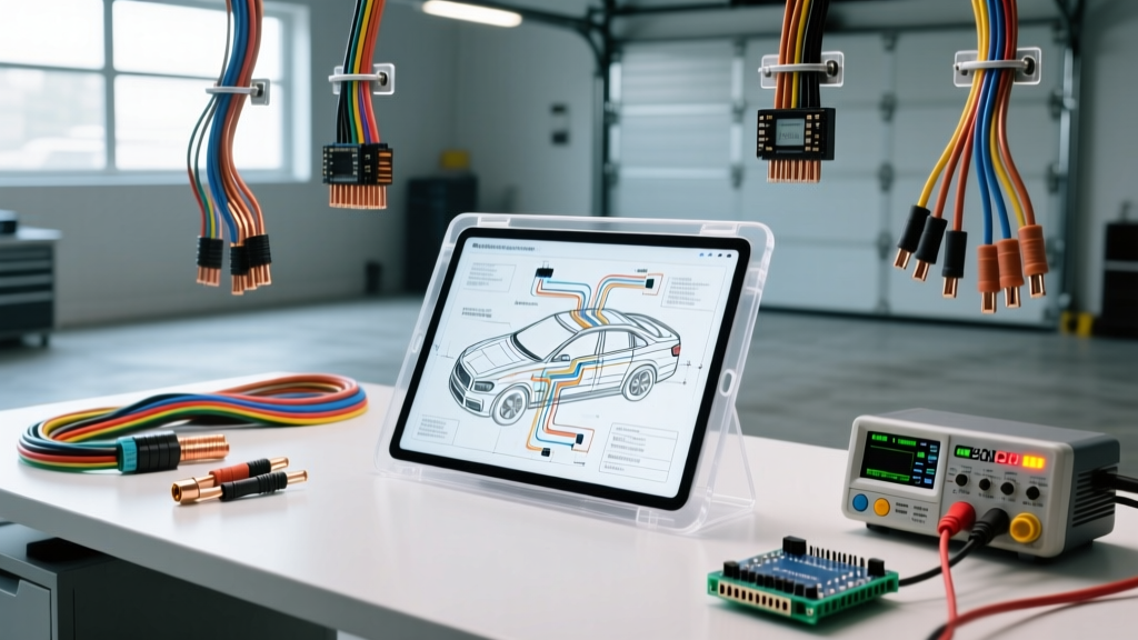
The Evolution of Auto Electrical Tools in Modern Architecture
Modern vehicles are rolling data centers, relying on high-speed multiplexed networks and pulse-width modulated (PWM) power circuits. In this environment, a standard Digital Volt-Ohm Meter (DVOM) is no longer sufficient. Because multimeters average voltage readings over time, they mask microsecond glitches in CAN bus arbitration or intermittent voltage drops across high-amperage starter circuits. To accurately diagnose contemporary vehicle electrical architecture, technicians must upgrade to advanced auto electrical tools capable of capturing transient waveforms, mapping network topology, and safely interrogating high-current pathways without inducing secondary failures.
This deep dive explores the technical specifications, application protocols, and real-world diagnostic strategies for professional-grade automotive electrical tools, focusing on Digital Storage Oscilloscopes (DSOs), high-amperage inductive clamps, and network breakout interfaces.
Digital Storage Oscilloscopes (DSO): The Ultimate Diagnostic Tool
A DSO is the cornerstone of advanced auto electrical tools. Unlike a DVOM, a DSO graphs voltage over time, allowing technicians to visualize the exact shape, frequency, and amplitude of a signal. This is critical when diagnosing Controller Area Network (CAN) bus communication errors or variable valve timing (VVT) solenoid PWM signals.
Sampling Rate and Bandwidth Requirements
When selecting a DSO for automotive diagnostics, bandwidth and sampling rate are paramount. High-speed CAN (ISO 11898-2) operates at 500 kbps (kilobits per second). To accurately reconstruct a 500 kHz square wave without aliasing, the oscilloscope must adhere to the Nyquist theorem, requiring a minimum sampling rate of 2 MS/s (Mega-samples per second), though 4 MS/s to 10 MS/s is recommended for capturing high-frequency electromagnetic interference (EMI) ringing on the bus.
| Automotive Protocol | Typical Speed | Minimum DSO Sampling Rate | Recommended Bandwidth |
|---|---|---|---|
| High-Speed CAN (Powertrain) | 500 kbps | 5 MS/s | 20 MHz |
| Low-Speed CAN (Comfort/Body) | 125 kbps | 1 MS/s | 10 MHz |
| LIN Bus (Sensors/Mirrors) | 19.2 kbps | 500 kS/s | 5 MHz |
| FlexRay (Chassis/Drive-by-Wire) | 10 Mbps | 100 MS/s | 50 MHz |
Probing CAN High (CAN-H) and CAN Low (CAN-L)
Standard high-speed CAN utilizes a twisted-pair topology. CAN-H rests at a recessive voltage of 2.5V and drives to a dominant 3.5V. CAN-L also rests at 2.5V but drops to a dominant 1.5V. When backprobing the OBD-II Data Link Connector (DLC), technicians must use specialized backprobe pins that match the terminal cavity. Forcing a standard multimeter probe into the DLC can spread the female terminals, causing intermittent fretting corrosion and secondary network faults.
Advanced DSO users utilize a Math Channel (CAN-H minus CAN-L) to create a differential signal. This math channel eliminates common-mode noise and EMI induced by adjacent high-current wiring, displaying a clean 0V to 2V differential waveform that the transceiver actually processes. For authoritative waveform libraries and math channel setups, technicians frequently reference Pico Technology CAN Bus Waveforms.
High-Current Inductive Clamps for Starter and Alternator Analysis
Diagnosing cranking and charging systems requires analyzing high-amperage circuits where standard multimeter shunts would melt or introduce dangerous resistance. Starter circuits on modern 5.3L to 6.7L engines routinely draw 400A to 600A during initial inrush, utilizing heavy-gauge wiring ranging from 4 AWG to 1/0 AWG.
Inrush Current and Voltage Drop Correlation
A high-amp hall-effect or inductive current clamp (such as the Fluke i410 or Pico TA018) is essential. By clamping over the main 4 AWG positive battery cable and simultaneously measuring voltage at the starter B+ terminal and the engine block ground, technicians can plot a dynamic voltage drop test against current draw.
- SAE J541 Standard: Dictates that the total voltage drop across the entire cranking circuit (positive and negative sides combined) must not exceed 0.5V at maximum cranking amperage.
- Connection Limits: No single connection (e.g., battery post to cable lug, or ground strap to chassis) should exhibit more than a 0.1V drop under load.
- Failure Mode: If the DSO shows a 450A draw but a 1.2V drop across the positive 1/0 AWG cable, the cable suffers from internal strand corrosion (green oxide) or a high-resistance crimp at the terminal lug, even if the external insulation appears intact.
Parasitic Draw Testing: Bypassing the Smart Battery Sensor
Parasitic draw testing has evolved drastically. Modern vehicles feature a Smart Battery Sensor (SBS) mounted directly on the negative battery terminal. The SBS monitors state-of-charge, temperature, and current, and communicates this data to the Body Control Module (BCM) via a single-wire LIN (Local Interconnect Network) bus.
The Sleep Mode Dilemma
If a technician physically disconnects the negative battery terminal to insert a multimeter in series, the SBS loses power. Upon reconnection, the BCM and SBS wake up, initiate a full network handshake, and begin recalibrating the battery state-of-charge. This process can draw 5 to 15 amps and take up to 45 minutes to return to a baseline sleep mode (typically <30mA). Repeatedly resetting the SBS can lead to premature battery failure and incorrect alternator load management.
Advanced auto electrical tools solve this using Low-Amp Inductive Clamps (capable of resolving 10mA changes) or dedicated Parasitic Draw Bypass Tools. These tools feature a heavy-duty shunt and a momentary bypass switch. The technician connects the tool in series with the negative terminal, leaves the bypass switch closed to maintain vehicle memory and SBS power, locks the vehicle, and waits for the modules to enter sleep mode. Once asleep, the technician opens the bypass switch, forcing the current through the precision shunt, and reads the true parasitic draw without waking the network. For detailed procedural guidelines on modern sleep-cycle testing, refer to the Fluke Parasitic Battery Drain Guide.
Breakout Boxes and Bus Topology Interrogation
When a CAN bus network crashes, the vehicle will exhibit a 'Christmas tree' dashboard, stalling, and a loss of communication with a scan tool. Diagnosing a network short requires isolating nodes without destroying wiring harnesses. This is where OBD-II Breakout Boxes become indispensable auto electrical tools.
Verifying Terminating Resistors and Pinouts
According to the SAE J1962 standard for diagnostic connectors, high-speed CAN-H is located at Pin 6, and CAN-L is at Pin 14. Pins 4 and 5 are designated for Chassis and Signal Ground, respectively. A breakout box plugs into the DLC, providing safe, accessible test points for DSO probes without risking terminal spread.
A critical diagnostic step is verifying the network's terminating resistors. A healthy high-speed CAN bus requires two 120-ohm resistors located at the opposing ends of the network backbone (typically inside the ECM and the TCM or BCM). Because these resistors are wired in parallel, a DVOM set to measure resistance across Pin 6 and Pin 14 (with the battery disconnected to prevent back-feeding voltage into the meter) should read exactly 60 ohms.
- Reading 120 Ohms: Indicates one terminating resistor is missing, open, or a module has lost power/ground and dropped off the bus.
- Reading <10 Ohms: Indicates a dead short between CAN-H and CAN-L, or a short to Pin 16 (Battery Positive).
- Reading 0 Ohms / OL (Open Line): Indicates a complete break in the twisted pair backbone or severe corrosion in a central star-point splice connector (common in European architectures like VW/Audi).
Conclusion: Investing in Diagnostic Precision
The transition from basic multimeters to advanced auto electrical tools is not merely a luxury; it is a technical necessity. Understanding the sampling limitations of your DSO, the AWG constraints of high-amperage circuits, and the LIN bus architecture of modern battery management systems separates parts-changers from true electrical diagnosticians. By leveraging oscilloscopes, high-amp inductive clamps, and topology breakout boxes, technicians can accurately map network faults, verify SAE-compliant voltage drops, and resolve complex parasitic draws with absolute precision.