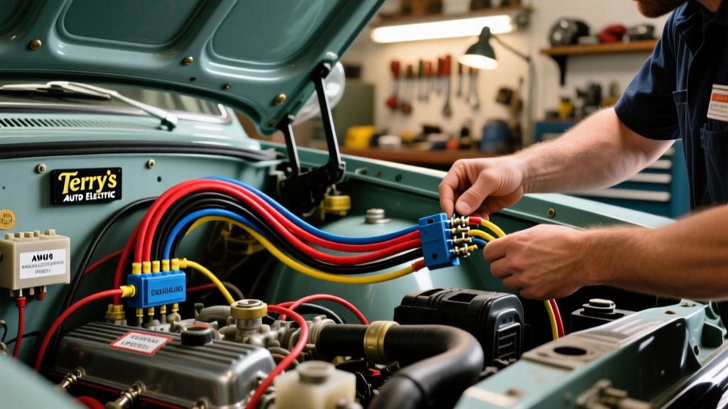
Upgrading Classic Vehicle Architecture with Terry's Auto Electric
Restoring a classic vehicle, such as a 1973-1987 Chevy C10 Square Body or a 1967-1972 Ford F-100, often reveals the critical failure point of the original electrical system: brittle, undersized, and degraded copper wiring. Upgrading to a modern, high-capacity universal kit, such as a Terry's Auto Electric 24-circuit custom wiring harness, replaces outdated point-to-point routing with a centralized, fused, and relay-driven architecture. This practical how-to guide details the exact installation methodology, from firewall bulkhead pass-throughs to high-amperage alternator integration, ensuring your classic truck's electrical system can safely handle modern loads like EFI, electric cooling fans, and high-output lighting.
Essential Tooling and Connector Preparation
Before unrolling the Terry's Auto Electric harness, you must assemble the correct terminal crimping and sealing tools. The kit relies heavily on Delphi Weather-Pack and Metri-Pack 280 series connectors for under-hood and sensor applications. Standard pliers will destroy the terminal tangs and compromise the moisture seals.
- Crimpers: Use a Delphi-specific Weather-Pack crimper (part number 12094429 equivalent) for 14-20 AWG stamped terminals.
- Heat Source: A variable temperature heat gun for sealing adhesive-lined polyolefin heat shrink tubing.
- Wire Strippers: Precision automatic strippers calibrated to SAE J1128 GXL/TXL wire insulation thicknesses to prevent nicking the copper strands.
- Hardware: #10-24 x 1/2 inch stainless steel pan-head screws and serrated flange nuts for mounting the main fuse block to the firewall or inner fender.
Routing the Main Harness and Firewall Pass-Through
The most common point of failure in custom harness installations is the firewall pass-through. The Terry's Auto Electric kit utilizes a heavy-duty rubber bulkhead grommet and a multi-pin connector block to separate the engine bay harness from the cabin dash harness.
Step-by-Step Firewall Routing
- Locate the OEM Pass-Through: On a C10, this is typically on the driver's side, just below the brake booster. If the factory hole is deformed, use a 2-inch bi-metal hole saw to cut a fresh opening in a flat section of the firewall.
- Deburr and Seal: File all sharp edges and apply a bead of black RTV silicone around the inner lip to prevent water intrusion into the cabin.
- Pull the Engine Bay Section: Feed the engine bay portion of the harness through the grommet. Crucial Tip: Always pull the harness by the thick outer loom, never by individual wires, to avoid stretching the copper strands or pulling terminals out of the connector housings.
- Secure the Drip Loop: Before the harness enters the bulkhead grommet, create a 'drip loop' (a downward U-shape) so water runs off the lowest point rather than tracking into the firewall.
Core Circuit Terminations and AWG Specifications
The Terry's Auto Electric harness uses color-coded, printed GXL wire. Proper termination requires matching the correct gauge to the specific circuit load. Below is the reference chart for the primary cabin and dash circuits.
| Circuit Function | Wire Color | AWG Size | Connector / Terminal Type |
|---|---|---|---|
| Ignition Switch (IGN) | Pink | 12 AWG | Packard 56 Female |
| Ignition Switch (ACC) | Brown | 12 AWG | Packard 56 Female |
| Headlight Feed (Relay 87) | Red | 10 AWG | Weather-Pack Male |
| Headlight Ground | Black | 10 AWG | 1/4' Ring Terminal |
| Instrument Cluster Illumination | Gray | 18 AWG | Metri-Pack 150 |
| Turn Signal (Front Left) | Light Green | 16 AWG | Weather-Pack Male |
| Turn Signal (Front Right) | Dark Green | 16 AWG | Weather-Pack Male |
| Electric Choke / EFI Main | White | 12 AWG | Inline Fuse Holder |
When terminating the ignition switch, ensure the Pink 12 AWG wire is routed to the 'IGN' post, providing switched 12V to the ignition coil, EFI ECU, and gauge cluster. The Brown 12 AWG wire connects to the 'ACC' post, powering the radio and wipers without the engine running.
High-Amp Charging System and Alternator Integration
Classic vehicles originally equipped with 40-amp externally regulated alternators require significant upgrades when swapping to a modern 100-amp or 140-amp internally regulated 'one-wire' or 'three-wire' alternator (such as a GM CS130 or Denso unit). MAD Electrical strongly advises against running the main charging current through the factory ammeter or bulkhead connectors, which causes severe voltage drops and fire hazards.
The 'Big Three' Wiring Upgrade
To properly integrate the Terry's Auto Electric harness with a high-output alternator, you must fabricate or utilize the kit's heavy-gauge charging cables:
- Alternator Output to Battery: Use 4 AWG stranded copper wire with a Mega Fuse (150A) installed within 18 inches of the battery positive terminal. Route this directly from the alternator BAT post to the starter solenoid battery post or directly to the battery.
- Engine Block Ground: Use 4 AWG black wire with heavy-duty 3/8-inch ring terminals. Connect from the negative battery post to a clean, bare metal surface on the engine block (preferably a cylinder head bolt).
- Engine to Chassis Ground: Use 6 AWG braided ground strap from the intake manifold or rear of the cylinder head to the firewall. This ensures the cabin electronics have a stable reference ground.
Torque Specification: When securing the 3/8-inch ring terminals to the cylinder head, torque the bolt to 20-25 ft-lbs. For battery post clamps, torque to 50-70 in-lbs to avoid cracking the lead posts.
Implementing Relay-Driven Headlight Circuits
One of the most significant advantages of the Terry's Auto Electric kit is the inclusion of relay-triggered headlight circuits. Factory headlight switches route the full 15-20 amp load through the dashboard switch, leading to melted plastic housings and dim lights due to voltage drop over long wire runs.
Bosch-Style Relay Pinout Configuration
The kit utilizes standard 30A ISO mini-relays. Wire the headlight relays using the following pinout:
- Pin 30 (Common Input): 10 AWG Red wire directly from the fuse block's 30A headlight fuse (fed by the battery).
- Pin 87 (Normally Open Output): 10 AWG Yellow (Low Beam) or Green (High Beam) wire routed to the headlight Weather-Pack connectors.
- Pin 86 (Coil Positive): 16 AWG wire connected to the output side of the factory headlight dimmer switch.
- Pin 85 (Coil Ground): 16 AWG Black wire grounded to the inner fender or radiator support.
By using this configuration, the factory dashboard switch only carries the minimal coil current (less than 0.5 amps), completely eliminating the risk of switch failure and ensuring full 14.2V reaches the headlight filaments.
Grounding Strategy: Star vs. Daisy Chain
Proper grounding is the backbone of any automotive electrical system. Avoid 'daisy-chaining' grounds (connecting a ground wire from the taillight to the bumper, then to the frame), as this creates variable resistance and causes back-feeding (e.g., brake lights illuminating when the turn signal is activated).
Instead, utilize a Star Grounding strategy. The Terry's Auto Electric harness provides multiple dedicated 10 AWG black ground wires with pre-crimped ring terminals. Group these grounds at centralized, dedicated grounding buss bars mounted to the inner fenders and the rear frame crossmember. Use a wire brush to remove all paint, powder coating, and rust from the mounting surface down to bare steel before securing the buss bar with stainless steel hardware and star washers to bite into the metal.
Troubleshooting Decision Tree
If you encounter electrical gremlins after the initial installation, follow this diagnostic tree before cutting or splicing any wires:
- Symptom: Headlights dim when the radiator fan kicks on.
Cause: Voltage drop on the main alternator feed or inadequate engine-to-chassis grounding.
Fix: Perform a voltage drop test across the 4 AWG alternator cable with the fan running. If the drop exceeds 0.2V, upgrade the cable or check the Mega Fuse connections. - Symptom: Gauges read erratically or peg to maximum.
Cause: Poor instrument cluster ground or 12V feed on the switched ignition circuit.
Fix: Check the 18 AWG Black ground wire at the back of the gauge cluster. Ensure it is grounded to a clean dash frame brace, not a painted surface. - Symptom: Starter clicks once but won't crank, and dash lights die.
Cause: High resistance at the battery terminals or the main 12 AWG Pink ignition feed dropping voltage below 9V during cranking.
Fix: Clean battery posts and verify the ignition switch is receiving a dedicated 12 AWG feed from the fuse block, independent of the starter solenoid 'I' terminal.
By adhering to these exact routing, crimping, and grounding methodologies, your Terry's Auto Electric harness installation will provide a reliable, show-quality electrical foundation capable of supporting modern automotive accessories for decades to come.