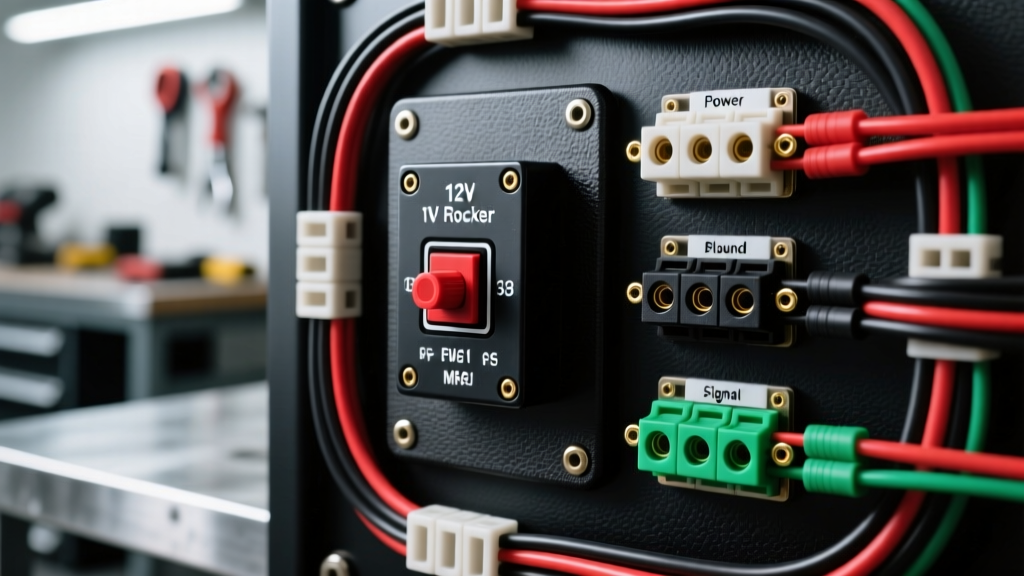
Introduction to Automotive Rocker Switch Topologies
Understanding how to hook up a rocker switch in a 12V DC automotive environment requires more than simply connecting power and ground. Modern off-road and auxiliary electrical systems rely on precise switch topologies to manage high-amperage loads like LED light bars, winches, and cooling fans. Whether you are installing a switch panel in a Jeep Wrangler, a Ford Super Duty, or a custom off-road buggy, misinterpreting the pinout of an illuminated rocker switch can lead to melted harnesses, blown fuses, or premature switch failure due to arcing.
This technical specification reference details the exact pin configurations, wire gauge requirements, and relay integration protocols for the two most common automotive rocker switches: the 3-pin SPST (Single Pole Single Throw) and the 5-pin SPDT (Single Pole Double Throw). All wiring recommendations adhere to SAE J1128 standards for low-tension primary cable and account for the 13.2V to 14.4V operating range of modern vehicle charging systems.
3-Pin SPST Rocker Switch Specification & Pinout
The 3-pin SPST rocker switch is the industry standard for simple On/Off auxiliary circuits. It features a single circuit path for the load and a dedicated circuit for the internal illumination (usually an LED or incandescent bulb). The most common form factor is the Contura V or standard 1.45-inch x 0.83-inch panel mount.
Terminal Identification & Wiring Sequence
Standard automotive 3-pin switches utilize 0.250-inch (6.35mm) FASTON male blade terminals. The pin numbering is typically stamped into the plastic housing near the terminals.
| Pin Number | Function | Wire Color (Standard) | Connection Destination |
|---|---|---|---|
| Pin 2 (Center) | Power Input (Line) | Red (14-16 AWG) | 12V+ Source via Inline ATC Fuse |
| Pin 3 (Top) | Power Output (Load) | Blue or White (14-16 AWG) | Accessory Positive OR Relay Pin 86 |
| Pin 1 (Bottom) | Illumination Ground | Black (18 AWG) | Chassis Ground or Battery Negative |
Expert Note on Illumination: In many modern LED-equipped 3-pin switches, the LED is polarity-sensitive. If you connect Pin 1 to 12V+ and Pin 2 to Ground, the switch will function mechanically, but the LED will not illuminate, and you risk damaging the internal diode. Always verify the internal schematic provided by manufacturers like Littelfuse or Carling Technologies before applying power.
5-Pin SPDT Rocker Switch Specification & Pinout
The 5-pin SPDT (Single Pole Double Throw) rocker switch is utilized for applications requiring directional control or dual-state operations, such as winch in/out controls, power window overrides, or antenna raise/lower mechanisms. It features an internal common terminal that routes power to one of two load terminals depending on the rocker's physical position.
Terminal Identification & Wiring Sequence
| Pin Number | Function | Wire Color (Standard) | Connection Destination |
|---|---|---|---|
| Pin 2 (Center) | Power Input (Common) | Red (12-14 AWG) | 12V+ Source via Inline Fuse |
| Pin 3 (Top) | Load 1 (Up Position) | Blue (12-14 AWG) | Motor/Actuator Terminal A |
| Pin 1 (Bottom) | Load 2 (Down Position) | Green (12-14 AWG) | Motor/Actuator Terminal B |
| Pin 4 | Illumination Ground | Black (18 AWG) | Chassis Ground |
| Pin 5 | Illumination Power | White (18 AWG) | 12V+ Ignition or Dash Lighting Circuit |
Failure Mode Warning: Using a 5-pin SPDT switch to directly reverse the polarity of a high-amperage DC motor (like a 40A winch) without a contactor or heavy-duty relay will cause severe internal arcing. The switch contacts are typically rated for only 20A continuous. Exceeding this will weld the internal copper contacts together, resulting in a runaway winch or motor. Always use the 5-pin switch to trigger a high-amperage solenoid or contactor pack.
Relay Integration: How to Hook Up a Rocker Switch to High Loads
When asking how to hook up a rocker switch for off-road lights or compressors, the most critical rule is to never route high-amperage loads directly through the switch panel. Doing so causes severe voltage drop across the dash harness and generates excessive heat at the switch terminals. Instead, use the rocker switch to trigger a standard ISO Mini Relay (30A/40A).
Standard ISO 4-Pin Relay Wiring via Rocker Switch
- Pin 30 (Relay Power In): Run 10 AWG or 12 AWG wire directly from the battery positive terminal through a 30A or 40A Maxi-fuse to Relay Pin 30.
- Pin 87 (Relay Load Out): Run 12 AWG wire from Relay Pin 87 to the positive terminal of your auxiliary accessory (e.g., LED light bar).
- Pin 85 (Relay Ground): Run 14 AWG wire from Relay Pin 85 to a clean, bare-metal chassis ground point. Use a star washer to ensure conductivity through the paint.
- Pin 86 (Relay Trigger): Run 16 AWG wire from Relay Pin 86 to Pin 3 (Load Out) of your 3-pin rocker switch.
- Switch Power: Run 16 AWG wire from an ignition-switched 12V+ source (like the rear window defroster fuse tap) to Pin 2 (Power In) of the rocker switch.
This configuration ensures that the heavy current (30A+) flows directly from the battery to the load via thick gauge wire, while the rocker switch only carries the minimal current required to energize the relay coil (typically 150mA to 200mA). This preserves the lifespan of the switch and prevents voltage drop at the accessory.
Wire Gauge (AWG) & Amperage Derating Chart
Selecting the correct wire gauge is paramount. Automotive environments require compensation for ambient engine bay heat and harness bundling. The following chart is based on TE Connectivity automotive wiring guidelines and SAE J1128 standards for single-conductor primary wire in free air.
| Max Continuous Load | Recommended AWG (Up to 10ft) | Recommended AWG (10ft - 20ft) | Inline Fuse Rating |
|---|---|---|---|
| 5 Amps | 18 AWG | 16 AWG | 7.5A ATC |
| 10 Amps | 16 AWG | 14 AWG | 15A ATC |
| 15 Amps | 14 AWG | 12 AWG | 20A ATC |
| 20 Amps | 12 AWG | 10 AWG | 25A ATC |
| 30 Amps | 10 AWG | 8 AWG | 40A Maxi |
Common Failure Modes & Troubleshooting Matrix
Even with correct pinout knowledge, environmental factors and poor termination practices lead to circuit failures. Use this diagnostic matrix to troubleshoot rocker switch installations.
| Symptom | Probable Cause | Technical Fix |
|---|---|---|
| Switch illuminates, but accessory does not power on. | Open circuit on Load (Pin 3) or failed relay coil ground. | Test Pin 3 for 12V+ with a multimeter while depressed. If 12V+ is present, check relay Pin 85 ground continuity. |
| Inline fuse blows immediately upon pressing the switch. | Dead short to ground on the Load wire or incorrect relay pinout. | Inspect the Load wire for chafing against the firewall. Verify relay Pin 87 is not shorted to Pin 85. |
| Switch housing melts or feels hot to the touch. | Exceeding amperage rating or high resistance at terminals. | Switch is carrying direct load >20A. Reroute circuit through a relay. Check for loose 0.250-inch crimps causing arcing. |
| LED illumination flickers when engine is running. | Alternator ripple voltage or poor ground connection. | Verify Pin 1 ground has less than 0.1V drop. Add a 100uF capacitor across the LED circuit if alternator ripple is severe. |
SAE Standards & Termination Best Practices
To ensure long-term reliability in high-vibration automotive environments, all connections to the rocker switch must utilize fully insulated, adhesive-lined heat shrink quick-disconnect terminals. Standard vinyl-insulated crimps will allow moisture ingress, leading to galvanic corrosion on the copper blade terminals.
When crimping, use a ratcheting crimper calibrated for 22-10 AWG terminals to ensure proper compression. The wire insulation should rest exactly at the terminal's brass barrel shoulder, while the bare copper strands should extend slightly past the end of the brass barrel to maximize surface area contact. Finally, always route switch panel wiring through split loom tubing or braided sleeving, securing it with Tesa tape every 6 inches to prevent abrasion against the dashboard sub-frame or roll cage tubing.