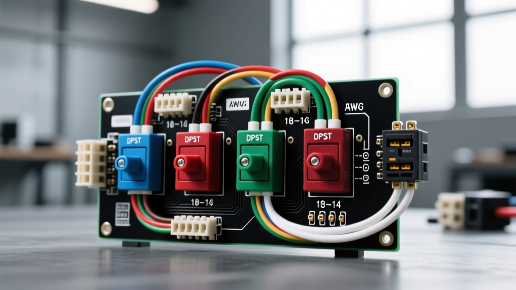
Decoding the Four Prong Rocker Switch Architecture
When outfitting a custom overland rig, marine vessel, or dedicated off-road vehicle, selecting the correct switching mechanism is critical for both operational safety and electrical longevity. The four prong rocker switch is a staple in custom automotive and marine installations, yet its internal architecture is frequently misunderstood by novice installers. Unlike the standard three-pin SPST (Single Pole, Single Throw) switch, a four-pin configuration generally falls into one of two distinct categories: the DPST (Double Pole, Single Throw) switch, or the SPST switch with an isolated, independent LED indicator circuit. Understanding the difference between these two architectures is the first step in designing a bulletproof custom wiring harness.
Variant A: The DPST (Double Pole, Single Throw) Configuration
The DPST four prong rocker switch acts as two separate SPST switches mechanically linked by a single actuator. This configuration features four main terminals: two input (line) terminals and two output (load) terminals. In advanced automotive applications, DPST switches are utilized to simultaneously break both the positive and negative legs of a circuit. This is a mandatory safety requirement in marine environments (per ABYC standards) and in high-vibration off-road applications where a chassis short could bypass a single-pole switch and cause a parasitic draw or electrical fire. Alternatively, a DPST switch can be used to independently trigger two separate relay coils from a single physical button press, such as simultaneously engaging a winch solenoid and an auxiliary cooling fan.
Variant B: SPST with Isolated LED Indicator Pins
The second common iteration of the four prong rocker switch is an SPST switch that includes a dedicated, electrically isolated LED indicator. Standard illuminated switches share the ground or power leg with the internal LED, meaning the LED only illuminates when the load is active. However, in complex custom dash panels, installers often require the LED to illuminate only when the vehicle's headlight circuit is active (dash dimming), or to indicate a fault condition independent of the switch's physical state. In this four-pin variant, Pins 1 and 2 handle the primary high-current load, while Pins 3 and 4 serve as the dedicated Anode (+) and Cathode (-) for the internal LED, allowing for completely separate control circuits.
Pinout Reference and Terminal Identification
Proper terminal identification is crucial. Relying solely on physical position can lead to catastrophic short circuits, as manufacturing molds vary between brands like Carling, Littelfuse, and generic importers. Always verify continuity with a digital multimeter (DMM) before applying power.
| Switch Type | Pin 1 | Pin 2 | Pin 3 | Pin 4 | Primary Use Case |
|---|---|---|---|---|---|
| DPST (Non-Illuminated) | Line A (Source 1) | Load A (Output 1) | Line B (Source 2) | Load B (Output 2) | Marine battery isolation, dual relay triggering |
| SPST (Isolated LED) | Line (Main 12V+) | Load (Switched Output) | LED Anode (+) | LED Cathode (-) | Custom dash panels, fault-indication lighting |
AWG Sizing, Contact Resistance, and Thermal Limits
A common and dangerous mistake in custom installations is sizing the wire based solely on the switch's stamped amperage rating (e.g., "20A 12VDC"). According to SAE J1128 standards for low-tension primary cable, wire gauge must be selected based on the total circuit length and the acceptable voltage drop, not just the switch's maximum thermal threshold. Furthermore, as a rocker switch ages, the internal copper or silver-alloy contacts degrade, increasing contact resistance. A switch rated for 20A may safely handle 20A when brand new, but at 18A with increased resistance, the internal housing can melt.
For automotive applications, we apply a strict 80% continuous load derating rule. If your accessory draws 16A continuously, you must use a switch rated for at least 20A, paired with 12 AWG SAE J1128 primary wire and a 20A ATO/ATC blade fuse.
| Max Continuous Load | Required Switch Rating | Min. Wire Gauge (SAE) | Recommended Fuse (ATO) |
|---|---|---|---|
| 5A | 10A | 16 AWG | 7.5A |
| 10A | 15A | 14 AWG | 10A |
| 15A | 20A | 12 AWG | 15A |
| 20A+ | N/A (Use Relay) | 10 AWG (Relay to Load) | 25A |
Relay Integration: Switching High-Amperage Inductive Loads
A four prong rocker switch should never be used to directly switch high-amperage inductive loads such as off-road LED light bars, winch solenoids, or air compressors. Inductive loads generate a massive reverse voltage spike (back-EMF) when the circuit is broken, which will pit and arc the internal contacts of the rocker switch, leading to rapid failure. Instead, the switch must be used as a low-current trigger for a standard Bosch-style ISO mini relay.
Wiring a Bosch-Style Relay with a 4-Prong DPST Switch
When using a DPST switch to control heavy auxiliary lighting via relays, you can utilize the dual poles to manage both the primary trigger and a secondary safety lockout or indicator circuit. Here is the professional wiring sequence for a standard 4-pin automotive relay (Pins 30, 87, 85, 86):
- Pin 30 (Power In): Run 10 AWG red wire directly from the battery positive terminal, protected by a 30A MAXI fuse within 6 inches of the battery.
- Pin 87 (Switched Output): Run 10 AWG blue wire to the positive terminal of your high-draw accessory (e.g., 40-inch LED light bar).
- Pin 85 (Relay Ground): Run 14 AWG black wire to a clean, bare-metal chassis ground point. Secure with a ring terminal and star washer.
- Pin 86 (Relay Trigger): Run 14 AWG yellow wire to Pin 2 (Load A) on your DPST four prong rocker switch.
- Pin 1 (Line A): Connect to a 12V ignition-switched source so the relays cannot be left on when the vehicle is parked.
- Pins 3 & 4 (Line B & Load B): Use the second pole to switch the ground path for a dedicated dash-mounted fault indicator LED, completing a secondary diagnostic loop.
Expert Note: When switching inductive relay coils, it is highly recommended to install a flyback diode (e.g., 1N4007) across pins 85 and 86, with the cathode (stripe) facing pin 86. This clamps the inductive kickback and protects sensitive solid-state vehicle ECUs from voltage spikes traveling back through the chassis ground. For deeper insights into relay coil suppression, refer to AutoShop 101's Automotive Electrical Guidelines.
Environmental Sealing and Terminal Crimping Standards
The environment dictates the hardware. For exterior cab installations or marine applications, you must specify an IP67-rated or IP68-rated sealed rocker switch. These feature silicone boots and epoxy-potted internal cavities to prevent moisture ingress. However, the switch body is only as secure as its terminations.
Never use standard vinyl-insulated butt connectors or open-barrel crimps on a four prong rocker switch located in high-vibration or high-moisture zones. You must use adhesive-lined, dual-wall marine heat shrink terminals. When heated, the inner thermoplastic adhesive melts and flows into the wire strands, creating a watertight seal that prevents capillary action from drawing moisture into the copper strands. Use a ratcheting crimping tool calibrated for closed-barrel terminals to ensure the correct compression ratio, avoiding both cold crimps (which cause voltage drop) and over-crimps (which shear the copper strands).
Advanced Troubleshooting: Voltage Drop and Backfeed
If your four prong rocker switch feels hot to the touch during operation, or if your connected LED accessories exhibit a faint "ghost glow" when the switch is in the OFF position, you are experiencing either excessive contact resistance or circuit backfeed.
- Thermal Runaway (Hot Switch): Perform a voltage drop test across the switch while under load. Place your DMM probes on the wire entering Pin 1 and the wire exiting Pin 2. A healthy switch should show a voltage drop of less than 0.1V. If the drop exceeds 0.3V, the internal contacts are pitted or oxidized, generating excess heat (Watts = Voltage Drop x Amperage). Replace the switch immediately.
- Ghosting / Backfeed: If you are using an SPST switch with an isolated LED (Variant B), ensure the LED Cathode (Pin 4) is tied to a true, switched ground. If Pin 4 is tied to a chassis ground that shares a return path with other active modules, a small leakage current can backfeed through the LED circuit, causing a dim illumination even when the primary switch is off. Use a dedicated ground bus bar to isolate indicator circuits from high-current return paths.
By adhering to these advanced architectural principles, AWG derating formulas, and relay integration techniques, your custom four prong rocker switch installations will meet OEM-level reliability standards. For comprehensive component specifications and lifecycle testing data, consult the Littelfuse Rocker Switch Catalog before finalizing your custom dash panel layout.