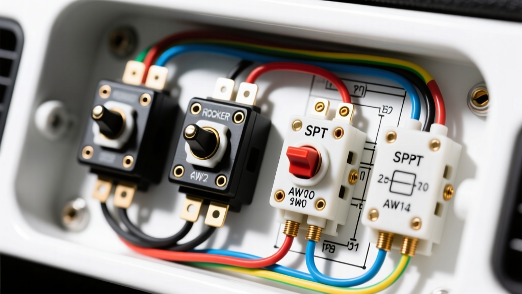
Understanding 3 Prong Rocker Switch Architecture
When designing a custom auxiliary switch panel for off-road lighting, winch controls, or onboard air compressors, selecting the correct switch topology is critical for safety and functionality. The term 3 prong rocker switch wiring generally refers to two distinct automotive switch architectures: the SPST (Single Pole, Single Throw) switch with an integrated LED indicator, and the SPDT (Single Pole, Double Throw) switch without an LED. Confusing these two configurations is a leading cause of short circuits and melted switch housings in custom 12V/14.4V DC automotive builds.
Unlike standard household AC switches, automotive rocker switches must handle high inrush currents, resist moisture ingress (IP65/IP68 ratings), and integrate seamlessly with vehicle CAN-bus or ignition-switched power distribution modules. This guide breaks down the exact pinouts, wire gauge requirements, and relay integration strategies for both 3-prong variants.
Pinout Configurations: SPST-LED vs. SPDT
Before cutting or crimping a single wire, you must identify the internal circuit topology of your switch. Most aftermarket automotive switches (such as those from Carling Technologies or Nilight) use standard 0.250-inch (6.35mm) spade terminals, but their internal routing differs vastly.
Architecture A: SPST (ON-OFF) with Integrated LED (3-Pin)
This is the most common switch found in off-road light bar panels. It features a single internal contactor for the load and a separate circuit for the LED backlight/indicator.
- Pin 2 (Bottom): +12V Power Input (from fused ignition or battery bus).
- Pin 3 (Middle): +12V Power Output (to the load or relay coil trigger).
- Pin 1 (Top): Ground (-) for the internal LED indicator.
Testing Note: If you apply +12V to Pin 2 and ground Pin 1, the LED will illuminate regardless of the switch position. The load only receives power when the rocker is toggled ON, bridging Pin 2 and Pin 3.
Architecture B: SPDT (ON-ON or ON-OFF-ON) without LED (3-Pin)
Used for selecting between two distinct circuits (e.g., switching between a main fuel tank and an auxiliary tank, or toggling between high/low beam HID ballasts).
- Pin 2 (Center): Common Power Input (+12V).
- Pin 1 (Top): Output A (Active in Position 1).
- Pin 3 (Bottom): Output B (Active in Position 2).
Product Comparison: Which 3-Prong Switch Do You Need?
| Feature | SPST with LED (3-Pin) | SPDT (3-Pin) |
|---|---|---|
| Primary Application | Activating single loads (LED pods, compressors) | Source selection, dual-circuit toggling |
| Internal Contacts | 1 Main Contactor, 1 LED Resistor Circuit | 1 Common, 2 Throw Contactors |
| Visual Feedback | Yes (Illuminates when load is active) | No (Requires external indicator LEDs) |
| Relay Compatibility | Directly triggers Bosch-style relay (Pin 86) | Can trigger dual relays or reverse polarity |
| Typical Amperage Rating | 20A @ 12VDC | 10A - 20A @ 12VDC |
Wire Gauge (AWG) and Thermal Derating
Automotive electrical systems operate nominally at 12.6V (engine off) and up to 14.4V (alternator charging). According to the SAE J1128 Standard for low-tension primary cable, wire sizing must account for both continuous current draw and voltage drop over the length of the run. A switch rated for 20A will suffer severe thermal degradation and contact pitting if pushed to its absolute limit in a high-ambient-temperature engine bay.
AWG Sizing Chart for 3-Prong Switches (14.4V System)
| Switch Rating | Recommended Wire Gauge (AWG) | Max Continuous Wattage (14.4V) | Inline Fuse Size (Max) |
|---|---|---|---|
| 10 Amp | 16 AWG | 144 Watts | 10A ATO/ATC |
| 20 Amp | 12 AWG | 288 Watts | 15A or 20A ATO/ATC |
| 30 Amp | 10 AWG | 432 Watts | 25A or 30A ATO/ATC |
Expert Tip: Always reference the Blue Sea Systems Circuit Protection Chart to match your wire gauge to the correct fuse size. The fuse protects the wire, not the switch. If you use 14 AWG wire on a 20A switch, the inline fuse must not exceed 15A to prevent the wire from melting before the fuse blows.
Wiring Scenarios and Diagrams
Scenario 1: Direct Load Wiring (Low Amperage LED Pods)
For accessories drawing less than 10A (e.g., a pair of 18W LED work lights drawing ~3A total), you can wire the load directly through the SPST 3-prong switch.
- Power In: Run 14 AWG Red wire from an ignition-switched fuse panel to Pin 2.
- Load Out: Run 14 AWG Blue wire from Pin 3 to the positive terminal of the LED pods.
- LED Ground: Run 18 AWG Black wire from Pin 1 to a clean, bare-metal chassis ground.
- Load Ground: Ground the LED pods directly to the chassis.
Scenario 2: Relay Integration (High Amperage Light Bars & Winches)
Never run high-amperage loads (like a 300W light bar drawing 25A) directly through a dashboard rocker switch. The thin copper traces inside the switch will overheat, causing voltage drop and potentially melting the plastic housing. Instead, use the switch to trigger a standard Bosch ISO Mini Relay.
- Switch Power (Pin 2): 16 AWG Red wire from an ignition-switched source.
- Relay Trigger (Pin 3): 16 AWG Blue wire to Relay Pin 86.
- Switch Ground (Pin 1): 18 AWG Black wire to chassis ground (illuminates the rocker LED).
- Relay Ground (Pin 85): 14 AWG Black wire to chassis ground.
- Relay High Current In (Pin 30): 10 AWG Red wire directly from the battery positive terminal, protected by a 30A Mega or ANL fuse within 18 inches of the battery.
- Relay Load Out (Pin 87): 10 AWG Red wire to the light bar positive terminal.
By utilizing a Littelfuse Automotive Relay, the switch only carries the ~150mA required to energize the relay coil, ensuring the switch runs cool and lasts the lifetime of the vehicle.
Terminal Crimping and Connector Selection
The physical connection to the 0.250-inch spade terminals is a frequent point of failure. Avoid cheap, uninsulated stamped brass crimp connectors. Instead, use heat-shrink, closed-barrel, nickel-plated crimp terminals. The heat shrink provides an IP67 moisture seal, preventing galvanic corrosion in wet environments, while the closed barrel prevents the wire strands from fraying and shorting against adjacent pins.
When crimping, always use a ratcheting crimper calibrated for AWG 12-16 insulated terminals. A proper crimp should withstand a 30-lb pull test without the wire slipping from the barrel.
Common Failure Modes and Troubleshooting
- Symptom: Switch housing is hot to the touch, and lights flicker.
Cause: Running high amperage directly through the switch without a relay, or using undersized wire causing severe voltage drop.
Fix: Upgrade to a relay-driven circuit and verify AWG sizing. - Symptom: The rocker switch LED stays on even when the switch is turned OFF.
Cause: Backfeed from the load circuit. This happens if the load ground is poor, and current seeks a path to ground through the switch's LED ground pin (Pin 1).
Fix: Check and clean the chassis ground for the actual accessory load. Ensure the switch LED ground (Pin 1) is tied to a dedicated, clean ground point. - Symptom: Switch feels 'mushy' or fails to click.
Cause: Internal contact pitting and carbon buildup from switching highly inductive loads (like air compressors or winch solenoids) without a flyback diode or snubber circuit.
Fix: Replace the switch and install a reverse-biased flyback diode across the inductive load's terminals to suppress voltage spikes.
Final Selection Advice
For 90% of custom automotive accessory builds, the SPST 3-prong switch with an integrated LED is the correct choice. It provides essential visual confirmation that a circuit is active, which is vital for safety when operating accessories like onboard air or auxiliary fuel pumps. Always pair your 3 prong rocker switch wiring with proper automotive-grade relays, sealed heat-shrink crimps, and SAE-compliant primary wire to ensure a reliable, fire-free installation.