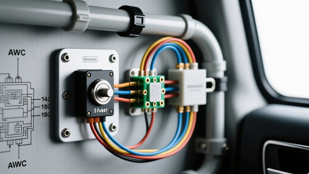
Anatomy of a 5-Pin 12V Lighted Rocker Switch
When integrating aftermarket accessories into a vehicle's electrical system, the 12V lighted rocker switch remains the industry standard for dashboard and center console mounting. Whether you are wiring an off-road LED light bar, an onboard air compressor, or a marine bilge pump, understanding the internal circuit of these switches is critical for a safe, reliable installation. The most ubiquitous variant in the custom automotive market is the 5-pin SPST (Single Pole, Single Throw) switch with dual-LED illumination. Unlike older incandescent models, modern LED-equipped switches are polarity-sensitive and require precise terminal identification to function correctly and avoid damaging the internal diode.
While premium switches like the Carling V-Series set the benchmark for marine and heavy-duty applications, the vast majority of aftermarket switch panels utilize a standardized generic 5-pin footprint. This walkthrough dissects the internal wiring diagram, pinout configurations, and the two primary installation scenarios: direct-load wiring and relay-triggered wiring.
Internal Wiring Diagram & Pinout Walkthrough
A standard 5-pin SPST rocker switch features three active terminals and two dummy pins used for structural alignment in the switch panel housing. The internal circuit consists of a primary mechanical wiper that bridges the input and output, alongside a parallel circuit housing the illumination LEDs and current-limiting resistors.
| Terminal | Function | Recommended Wire Color | AWG Size | Connection Notes |
|---|---|---|---|---|
| Pin 2 | +12V Power Source (Input) | Red | 18 AWG | Connects to fused ignition or constant 12V source. |
| Pin 3 | Chassis Ground | Black | 18 AWG | Completes the internal LED circuit. Must be chassis or battery negative. |
| Pin 5 | Switched +12V Output (Load) | Blue or Yellow | 18 AWG (Relay) / 12 AWG (Direct) | Routes power to the accessory or relay trigger terminal. |
| Pins 1 & 4 | Dummy / Alignment Pins | N/A | N/A | Do not connect. Used for physical retention in the bezel. |
Crucial Polarity Warning: If you accidentally swap Pin 2 (Power) and Pin 3 (Ground), the switch will still mechanically pass power from Pin 2 to Pin 5 if wired inversely, but the internal LEDs will not illuminate. Prolonged reverse polarity can overheat and destroy the internal surface-mount resistors and LEDs. Always verify your source wire with a digital multimeter (DMM) before crimping.
Scenario 1: Direct Load Wiring (Under 10 Amps)
Direct wiring is acceptable only for low-draw accessories that pull less than 10 amps continuously. Examples include interior LED dome kits, USB charging modules, or low-amperage solenoid triggers. Most generic aftermarket rocker switches are rated for 20A at 12V DC, but running them at maximum capacity generates excessive heat at the terminal spades, leading to melted plastic housings. For direct loads, we derate the continuous capacity to 10A for safety.
Step-by-Step Direct Wiring Walkthrough
- Source the Power: Use an Add-A-Circuit (fuse tap) in the vehicle's interior fuse box to tap an ignition-switched circuit. Run an 18 AWG red wire from the fuse tap to Pin 2 on the rocker switch. Install an inline 5A ATC blade fuse near the tap.
- Establish Ground: Crimp a ring terminal to one end of an 18 AWG black wire and secure it to a clean, unpainted chassis ground point under the dash. Connect the opposite end to Pin 3.
- Route the Load: Run a 14 AWG blue wire from Pin 5 through the firewall to the accessory's positive input terminal.
- Ground the Accessory: Complete the circuit by grounding the accessory's negative terminal directly to the vehicle chassis or battery negative.
Scenario 2: Relay-Triggered Wiring (High-Draw Accessories)
For high-draw accessories like 300W LED light bars (approx. 22A), winch solenoids, or air compressors, the rocker switch should never carry the main load. Instead, the switch acts as a low-amperage trigger for a Bosch-style ISO 5-pin mini relay. This prevents voltage drop across the dashboard wiring and protects the switch's internal copper wiper from arcing and thermal failure.
Integrating the 5-Pin Bosch Relay
A standard automotive relay features five terminals: 30 (Common/Power In), 85 (Coil Ground), 86 (Coil Trigger), 87 (Normally Open/Load Out), and 87a (Normally Closed). For standard accessory switching, we only use 30, 85, 86, and 87.
- Switch Wiring: Wire Pin 2 to a fused 12V ignition source (18 AWG). Wire Pin 3 to chassis ground (18 AWG). Wire Pin 5 to Relay Terminal 86 using 18 AWG wire.
- Relay Coil Ground: Wire Relay Terminal 85 to a clean chassis ground using 18 AWG wire.
- High-Current Power Feed: Run a heavy-gauge wire (10 AWG or 12 AWG, depending on the load) directly from the vehicle's battery positive terminal to Relay Terminal 30. You must install an inline Maxi or ANL fuse within 8 inches of the battery terminal.
- Load Output: Run the same heavy-gauge wire from Relay Terminal 87 to the positive terminal of your high-draw accessory.
Wire Gauge Selection & Voltage Drop Mitigation
Selecting the correct American Wire Gauge (AWG) is dictated by the SAE J1128 standard for low-tension primary cable, factoring in both amperage and the total length of the wire run. Voltage drop is the silent killer of aftermarket lighting; a 12V light bar receiving only 10.5V due to undersized wiring will draw more amperage to compensate, generating excess heat and drastically reducing lumen output.
| Wire Gauge (AWG) | Max Amperage (Chassis Wiring) | Typical Application | Inline Fuse Rating |
|---|---|---|---|
| 18 AWG | 10 Amps | Switch trigger legs, relay coils, interior LEDs | 5A - 10A |
| 14 AWG | 15 Amps | Short-run auxiliary lights, horn relays | 15A |
| 12 AWG | 20 Amps | Standard 200W-300W LED light bars, 12V fridges | 20A |
| 10 AWG | 30 Amps | Air compressors, winch control solenoids, inverters | 30A |
For runs exceeding 15 feet (such as routing power from the engine bay to the rear cargo area of a Jeep Wrangler or SUV), always step up one gauge size to mitigate voltage drop. According to Blue Sea Systems circuit protection guidelines, the fuse must always be sized to protect the wire, not the accessory. If you are using 12 AWG wire, the inline fuse must not exceed 20A, regardless of the accessory's stated draw.
Professional Termination and Crimping Standards
The most common point of failure in custom 12V rocker switch installations is poor terminal crimping. The standard terminal size for aftermarket rocker switches is the 0.250-inch (6.3mm) female spade. Do not use slip-on, non-insulated push connectors; vibration from the vehicle chassis will rattle them loose, causing arcing and potential electrical fires.
Use fully insulated, nylon-crimped female spade terminals. Strip the wire precisely to the shoulder of the terminal barrel—leaving exposed copper invites corrosion and short circuits. Utilize a ratcheting crimp tool calibrated for insulated terminals to ensure a gas-tight mechanical bond. Finally, apply 3:1 adhesive-lined marine heat shrink over the crimp barrel. The internal adhesive melts and seals the wire strands, preventing moisture wicking, which is especially critical in marine and open-top off-road vehicles.
Troubleshooting Common Installation Failures
When a custom switch panel fails to operate correctly, use this diagnostic decision tree to isolate the fault:
Symptom: Switch Illuminates, But Accessory Does Not Power On
- Cause 1: Missing Accessory Ground. The switch LED circuit is independent of the load circuit. The switch is receiving power and ground, but the accessory lacks a return path. Fix: Test accessory ground with a DMM continuity tester.
- Cause 2: Voltage Drop on Load Wire. The wire gauge is too small for the distance, dropping the voltage below the accessory's operational threshold. Fix: Measure voltage at the accessory terminals while the circuit is under load.
- Cause 3: Blown Inline Fuse. A short circuit in the load wire caused the fuse to blow, but the switch remains illuminated because it is on a separate fused tap. Fix: Inspect load wiring for pinched insulation and replace the fuse.
Symptom: Switch Feels Hot to the Touch or Smells Like Melting Plastic
- Cause: Exceeding Internal Wiper Capacity. You have wired a high-draw accessory (e.g., a 25A compressor) directly through the switch without a relay. The internal copper contacts are overheating due to excessive resistance. Fix: Immediately disconnect power. Rewire the circuit using a Bosch-style relay so the switch only carries the ~0.2A relay coil trigger current.
Symptom: Switch Works, But LEDs Do Not Illuminate
- Cause: Reversed Polarity or Missing Pin 3 Ground. As noted, LED switches require a dedicated ground path for illumination. If Pin 3 is left floating, the LEDs will not light. If Pin 2 and Pin 3 are swapped, the internal diode blocks the LED circuit. Fix: Verify Pin 2 is +12V and Pin 3 is Ground using a multimeter.
Authoritative References
- SAE International J1128 - Low Tension Primary Cable Standard for automotive wire gauge and insulation specifications.
- Blue Sea Systems - Circuit Protection and Voltage Drop Calculation Guidelines for marine and off-road DC systems.
- Carling Technologies - V-Series and Contura Rocker Switch Datasheets for terminal pinouts and internal circuit schematics.