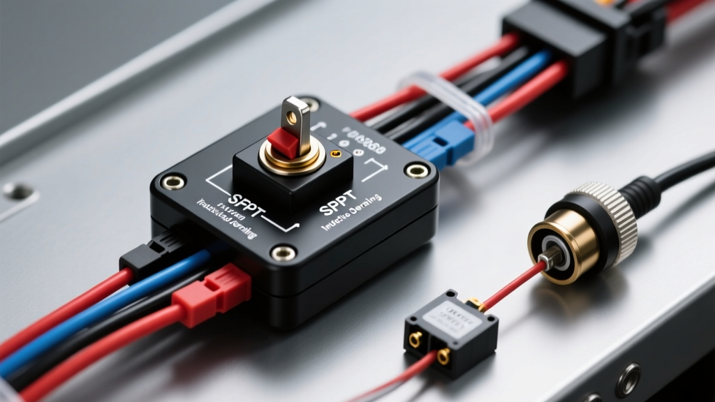
Introduction to Single Pole Rocker Switch Architectures
In the realm of custom automotive and overland electrical systems, the single pole rocker switch remains the foundational interface for driver-controlled accessories. Whether you are wiring a 40-inch LED light bar, a dual-battery isolator solenoid, or an onboard air compressor, understanding the internal mechanics, load derating curves, and proper relay integration of these switches is critical for long-term reliability. While often colloquially referred to by their physical form factor (e.g., Carling V-Series or Contura V), electrically, these components are defined by their pole and throw configurations. The most common variant for simple ON/OFF accessory control is the Single Pole Single Throw (SPST) switch, though Single Pole Double Throw (SPDT) configurations are frequently utilized for polarity-reversing circuits like linear actuators and power windows.
Internal Metallurgy and DC Arc Suppression
Unlike household AC circuits, which naturally extinguish electrical arcs 120 times per second as the sine wave crosses zero, 12VDC automotive circuits sustain arcs until the physical gap between the contacts is wide enough to break the plasma bridge. This makes the contact metallurgy inside a high-quality single pole rocker switch paramount.
Silver Cadmium Oxide (AgCdO) vs. Silver Nickel (AgNi)
Premium automotive rocker switches utilize Silver Cadmium Oxide (AgCdO) contacts. The cadmium oxide inclusions act as arc-quenching agents, preventing contact welding and pitting when breaking highly inductive DC loads. Conversely, cheaper switches often use Silver Nickel (AgNi), which is suitable for low-draw resistive loads (like interior LED map lights) but will rapidly degrade, carbon-track, and eventually fuse shut when used to directly switch inductive loads like fuel pumps or winch contactors. According to Carling Technologies DC Derating Guidelines, utilizing the correct contact alloy is the first line of defense against catastrophic thermal runaway in custom switch panels.
The Critical Math: Resistive vs. Inductive Load Derating
A common and dangerous mistake in custom installation is assuming a switch stamped with "20A 12VDC" can safely handle a 20A continuous inductive load. This ignores the physics of inrush current. When an electric motor (like an air compressor or winch) starts, it experiences Locked Rotor Amps (LRA), which can be 5 to 7 times higher than its Full Load Amps (FLA) running current. If you use a 20A SPST switch to directly power a 15A compressor, the 90A inrush spike will instantly pit the contacts, leading to localized resistance, voltage drop, and eventually a melted switch housing.
| Load Type | Example Accessory | Switch Rating (20A) | Safe Direct Switching Limit | Inrush Multiplier |
|---|---|---|---|---|
| Resistive | Heated Seats, Halogen Lamps | 20A @ 12VDC | 15A (Continuous) | 1.0x - 1.2x |
| Inductive | Winches, Air Compressors, Fuel Pumps | 20A @ 12VDC | 3A - 5A (Max) | 5.0x - 7.0x (LRA) |
| Capacitive | Large Inverters, Amplifier Banks | 20A @ 12VDC | 2A (Without Pre-charge) | 10.0x+ (Spike) |
| LED Lighting | LED Light Bars, Rock Lights | 20A @ 12VDC | 15A (Continuous) | 1.0x (Driver regulated) |
Standard 3-Pin SPST Pinout and LED Illumination
The standard Contura-style SPST single pole rocker switch features three terminals on the rear housing. Understanding this pinout is essential for proper dashboard illumination and preventing parasitic battery drain.
- Pin 1 (Load / Output): Connects to the accessory or the relay coil. This pin only receives voltage when the switch is in the ON position.
- Pin 2 (Source / Input): Connects to the switched or constant 12V+ power source. This is the common feed for the internal contactor.
- Pin 3 (Ground / Illumination): Connects to chassis ground. This pin completes the circuit for the internal LED indicator. Note that the upper and lower LEDs in a Contura switch often have independent internal resistors (typically 1,000 ohms for 12V systems), but they share this common ground path.
Pro-Tip: If you wire Pin 2 to a constant 12V battery source and Pin 3 to a chassis ground, the switch's internal LED will remain illuminated 24/7. While the current draw is minimal (approx. 15mA), over weeks of vehicle storage, this parasitic drain can deplete a standard lead-acid starter battery. Always route Pin 2 through an ignition-switched fuse tap or a master battery isolator bus.
High-Current Integration: Wiring a 40A Bosch-Style Relay
Because of the inductive derating limits mentioned above, a single pole rocker switch should almost never be used to directly switch loads exceeding 10A. Instead, the switch should be used to trigger the low-current coil of an ISO 7588 compliant automotive relay. Below is the exact specification for wiring a 40A relay to control a high-draw accessory like a 120W LED light bar or a 150W solenoid valve.
Required Materials and Wire Gauges
- Main Power Feed (Pins 30 & 87): 10 AWG TXL (Cross-linked polyethylene) wire. TXL is rated for 125°C and features a thin insulation wall, making it ideal for routing through tight firewall grommets and engine bays.
- Switch/Coil Circuit (Pins 85 & 86): 18 AWG GXL wire.
- Fusing: 15A ATO blade fuse for the main 10 AWG feed; 3A Mini fuse for the 18 AWG switch trigger wire.
- Terminals: Nylon-insulated heat-shrink ring terminals and butt splices to prevent strand fraying under SAE J1678 vibration standards.
Step-by-Step Wiring Sequence
- Battery to Relay (Pin 30): Run 10 AWG TXL from the positive battery terminal to Pin 30 on the relay. Install the 15A ATO fuse holder within 6 inches of the battery terminal to protect against dead shorts.
- Relay to Load (Pin 87): Run 10 AWG TXL from Pin 87 to the positive input of your accessory. Ground the accessory directly to a clean, bare-metal chassis point using a star washer to bite through paint and primer.
- Switch Power (Pin 2): Run 18 AWG GXL from a fuse-box ignition source (via an add-a-circuit with a 3A fuse) to Pin 2 on the single pole rocker switch.
- Switch to Relay Coil (Pin 1 to Pin 86): Run 18 AWG GXL from Pin 1 on the switch to Pin 86 on the relay. When the switch is toggled ON, 12V flows through this wire to energize the electromagnetic coil.
- Coil Ground (Pin 85): Run 18 AWG GXL from Pin 85 on the relay to a solid chassis ground.
- Switch Illumination (Pin 3): Run 18 AWG GXL from Pin 3 on the switch to a chassis ground to complete the internal LED circuit.
Environmental Sealing and Ingress Protection (IP68)
For exterior switch panels, open-top Jeeps, or marine applications, the environmental rating of the single pole rocker switch is non-negotiable. High-grade switches feature an IP68 rating, meaning they are completely dust-tight and can withstand continuous submersion in water beyond 1 meter. This is achieved through a combination of a neoprene front gasket, a silicone O-ring seal around the rocker actuator pivot, and an ultrasonically welded rear housing. When installing these in a custom CNC-cut aluminum or polymer switch pod, ensure the panel cutout is exactly 1.45" x 0.83" (37mm x 21mm) with a 0.06" to 0.12" panel thickness tolerance. A loose cutout will compromise the neoprene gasket compression, allowing capillary action to draw moisture behind the dashboard.
Diagnostic Troubleshooting: The Voltage Drop Test
When a custom accessory fails to operate, or a switch feels unusually hot to the touch, the internal contacts are likely suffering from carbon tracking or oxidation. Do not rely on a simple continuity test; a multimeter's continuity mode uses less than 1mA of current and will show a "closed" circuit even on heavily degraded contacts that will fail under a 10A load.
Instead, perform a dynamic voltage drop test across the switch while the circuit is under load:
- Turn the accessory ON so current is flowing through the circuit.
- Set your digital multimeter to the DC Millivolt (mV) scale.
- Place the red probe on Pin 2 (Source) and the black probe on Pin 1 (Load).
- Read the voltage drop. A healthy Silver Cadmium Oxide contact will show a drop of less than 50mV (0.050V).
- If the reading exceeds 100mV (0.100V), the internal resistance is generating excess heat (calculated via Joule's Law: P = I²R). The switch must be replaced immediately to prevent a localized electrical fire.
Solid-State Alternatives and CAN-Bus Integration
While the mechanical single pole rocker switch is a staple, advanced modern builds are increasingly utilizing these switches merely as low-current signal inputs for Solid State Relays (SSRs) or Vehicle Management Modules (VMMs) like the sPOD or C-Bus systems. By wiring the single pole switch to a high-impedance digital input, the switch carries virtually zero current (often less than 5mA). This completely eliminates mechanical contact wear, allows for software-defined delay timers, and enables pulse-width modulation (PWM) dimming of LED lighting directly from the master control unit, representing the cutting edge of custom automotive electrical integration.
For further reading on primary cable insulation types and temperature ratings referenced in this guide, consult the SAE J1128 Low Tension Primary Cable Standards documentation to ensure your custom harness meets OEM-level safety thresholds.