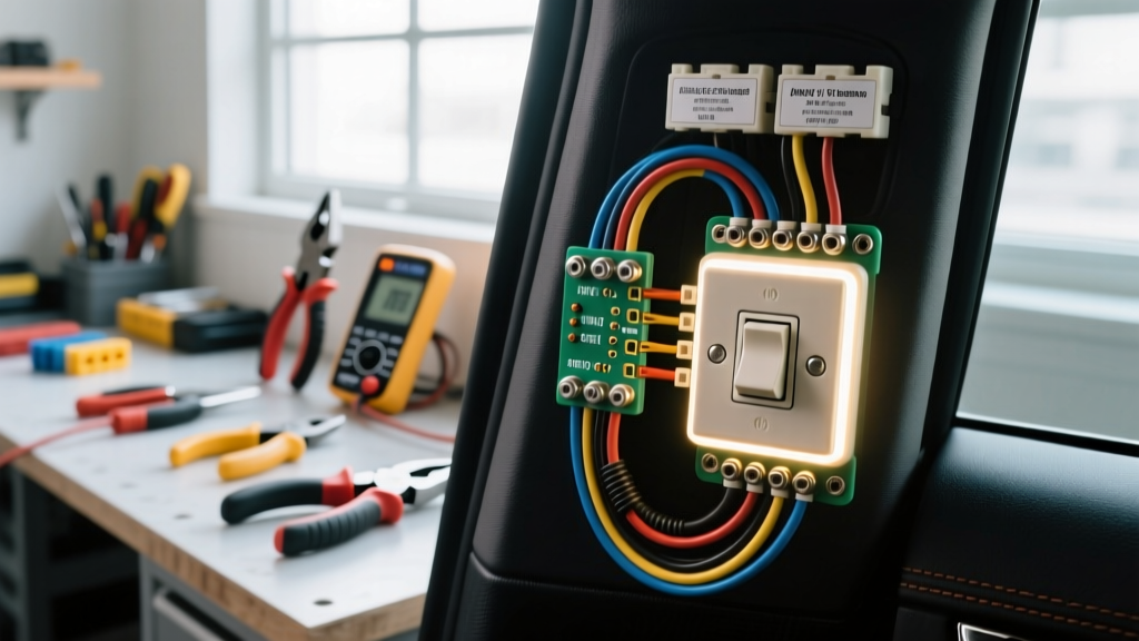
The True Cost of Lighted Rocker Switch Wiring: Budget vs. Professional Grade
When integrating aftermarket accessories like LED light bars, winches, or onboard air compressors, lighted rocker switch wiring is the critical interface between the driver and the electrical system. However, the market is flooded with sub-par $15 switch kits that compromise vehicle safety. As an automotive electrical specialist, I frequently diagnose melted dash panels, parasitic battery drains, and voltage drops traced back to cheap switches and improper tooling. This analysis breaks down the real costs and tool requirements for executing a reliable, marine-grade 12V rocker switch installation.
Component Cost Breakdown: The Hidden Price of Cheap Switches
Most budget rocker switch kits found on mass-market retail sites utilize Copper-Clad Aluminum (CCA) wire, non-ratcheting stamped brass terminals, and non-sealed switch housings. While the upfront cost is low, the failure rate in high-vibration, high-moisture environments (like off-road or marine applications) is exceptionally high. Professional installations rely on IP68-sealed switches, such as the Carling Technologies V-Series Contura switches, paired with cross-linked polyethylene (GXL/TXL) automotive wire.
| Component Category | Budget Kit (Mass Market) | Professional/Marine Grade | Failure Mode of Budget Option |
|---|---|---|---|
| Switch Housing | $4 - $8 (Non-sealed) | $15 - $25 (IP68 Sealed) | Internal corrosion, LED failure, short circuits |
| Primary Wire | $10 (16 AWG CCA) | $25 (12 AWG GXL Tinned Copper) | CCA wire oxidizes, increases resistance, melts under load |
| Terminals | $3 (Non-insulated brass) | $12 (Nylon insulated, ratcheted) | Vibration loosens crimp, causing arcing and heat |
| Circuit Protection | $2 (Glass AGC Fuses) | $15 (ATO/ATC Blade & Breaker) | Glass fuses shatter; lack of waterproof fuse holders |
| Total Material Cost | ~$19.00 | ~$67.00 | Risk of dash fire or accessory failure |
While the professional setup costs roughly $48 more per circuit, it eliminates the hidden costs of troubleshooting parasitic draws and replacing melted wiring harnesses. For high-draw accessories (e.g., a 140W LED light bar pulling 11.6A at 12V), upgrading to 12 AWG GXL wire and a 20A ATO fuse is non-negotiable. Always adhere to the SAE J1128 Low-Tension Primary Cable Standard when selecting wire for engine bay or chassis routing.
Essential Tooling: Why Ratcheting Crimpers Are Mandatory
The most common point of failure in lighted rocker switch wiring is not the switch itself, but the terminal crimp. A poor crimp introduces electrical resistance. According to Ohm's Law, increased resistance under a heavy load generates heat. If you are wiring a 12 AWG circuit feeding a 15A load, a loose terminal will generate enough heat to melt the switch's plastic housing from the inside out.
Tooling Tiers and Return on Investment (ROI)
| Tool Category | Budget Tier ($10-$20) | Professional Tier ($40-$150) | Expert Recommendation |
|---|---|---|---|
| Wire Crimper | Non-ratcheting pliers | Ratcheting terminal crimper (e.g., IWISS, Knoweasy) | Professional: Ratcheting tools ensure a uniform, gas-tight crimp every time, preventing wire pull-out. |
| Wire Stripper | Manual gauge-specific strippers | Automatic self-adjusting strippers (e.g., Klein 11055) | Professional: Prevents nicking the copper strands, which reduces the wire's ampacity and creates a break point. |
| Heat Source | BIC Lighter / Match | Milwaukee M18 Heat Gun or Butane Micro-Torch | Professional: Lighters leave carbon deposits and unevenly shrink tubing. A heat gun ensures adhesive-lined heat shrink seals properly. |
| Diagnostic Meter | $15 Basic Multimeter | Fluke 87V or Power Probe III | Professional: Accurate millivolt reading is required to diagnose voltage drop across the switch contacts. |
Investing $60 in a high-quality ratcheting crimper and a set of adhesive-lined, 3:1 shrink ratio heat shrink tubes will save you hours of frustrating diagnostics later. When wiring the 1/4-inch (6.35mm) female quick-disconnect terminals to the rocker switch pins, the ratcheting crimper ensures the wire barrel and insulation barrel are compressed to the exact manufacturer specifications.
Technical Reference: Switch Pinouts and Wiring Specifications
Understanding the internal architecture of your rocker switch is vital for proper illumination and load management. The most common configurations are SPST (Single Pole, Single Throw) and DPDT (Double Pole, Double Throw). Below is the standard pinout reference for a 5-pin SPDT (ON-OFF-ON) and a 3-pin SPST (OFF-ON) switch, commonly used in custom dash panels.
| Switch Type | Pin Number | Function | Recommended Wire Color | AWG Size (Up to 15A Load) |
|---|---|---|---|---|
| 3-Pin SPST (OFF-ON) | Pin 2 | +12V Source Input (from Fuse/Breaker) | Red | 12 AWG |
| Pin 3 | +12V Output (to Accessory/Relay Coil) | Blue | 12 AWG (or 18 AWG to Relay) | |
| Pin 1 | Ground (for Internal LED Illumination) | Black | 18 AWG | |
| 5-Pin SPDT (ON-OFF-ON) | Pin 2 | +12V Source Input | Red | 12 AWG |
| Pin 1 | Output 1 (e.g., Winch IN / Relay A) | Blue | 12 AWG | |
| Pin 3 | Output 2 (e.g., Winch OUT / Relay B) | Yellow | 12 AWG | |
| Pins 7 & 8 | Grounds for Upper/Lower LEDs (if equipped) | Black | 18 AWG |
Note: When using a lighted rocker switch to trigger a high-draw accessory (over 15A), the switch should ONLY carry the low-amperage load of the relay coil (typically 0.5A to 1.5A). In this scenario, Pins 2 and 3 can be safely wired with 16 or 18 AWG wire, while the heavy 10 AWG or 8 AWG wiring runs directly from the battery to the relay, and from the relay to the accessory. Always follow Blue Sea Systems Circuit Protection Guidelines to ensure your primary feed is fused within 7 inches of the battery positive terminal.
Common Failure Modes and Troubleshooting
Even with premium components, improper technique can lead to system failures. Here is a diagnostic decision tree for the most common issues encountered in lighted rocker switch wiring:
1. The LED Illuminates, But the Accessory Does Not Engage
- Cause: Voltage drop across the switch contacts or a faulty ground at the accessory.
- Diagnostic Step: Set your multimeter to DC Volts. Place the red probe on Pin 3 (Output) and the black probe on a known good chassis ground while the switch is ON. If you read 10.5V or lower (on a 12.6V system), the switch contacts are degraded, or the wire gauge is too small for the distance.
- Fix: Upgrade to a relay-driven circuit where the switch only handles the relay coil ground/trigger.
2. The Switch LED 'Ghost Glows' When Turned Off
- Cause: Backfeeding through the ground circuit. This happens frequently when the LED ground (Pin 1) is tied into a shared dash illumination circuit (like the headlight dimmer switch) rather than a dedicated chassis ground, or when using solid-state relays with internal bleed resistors.
- Fix: Reroute Pin 1 to a dedicated, clean chassis ground point. Use a star washer to bite through the paint and ensure bare metal contact.
3. Melted Terminal or Switch Housing
- Cause: High resistance at the crimp joint due to using non-ratcheting pliers, or utilizing CCA wire which oxidizes rapidly under the terminal barrel.
- Fix: Cut back the wire to fresh, unoxidized copper. Strip using proper gauge settings, and apply a new ratcheted crimp with adhesive-lined heat shrink to seal out moisture.
Final Verdict on Budget Allocation
Proper lighted rocker switch wiring is an exercise in risk management. Skimping on $40 worth of GXL wire, IP68 sealed switches, and a ratcheting crimper exposes your vehicle to electrical fires and leaves you stranded when an accessory fails on the trail. By allocating your budget toward marine-grade components and precision tooling, you ensure a reliable, weatherproof, and professional-tier electrical system that will outlast the vehicle itself.