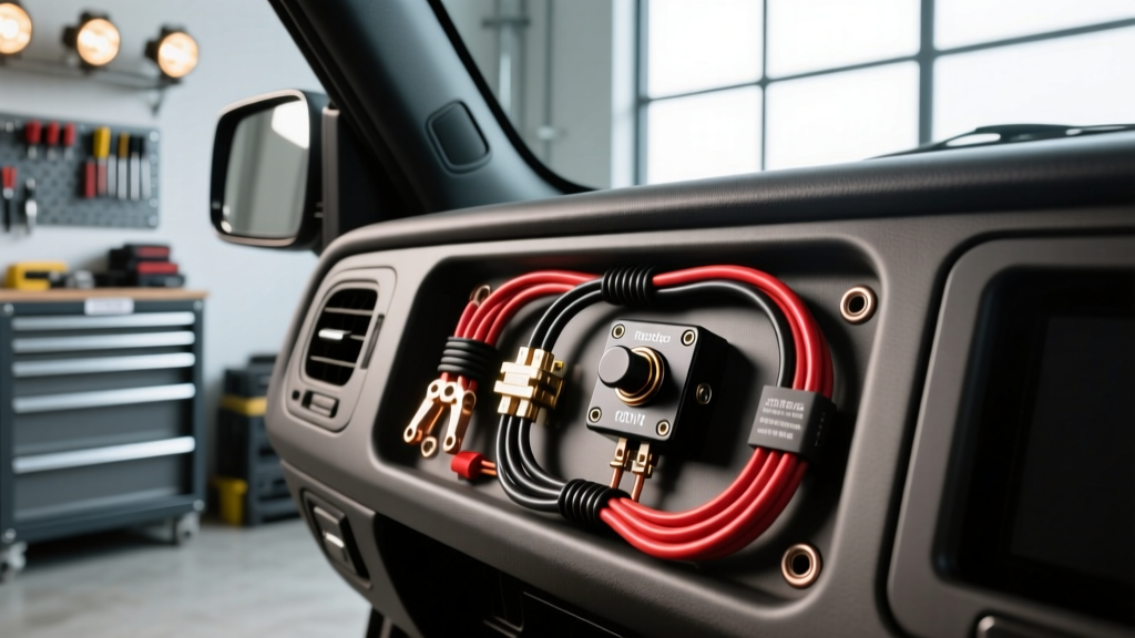
Introduction to 12V LED Rocker Switches
When outfitting a Jeep Wrangler, Toyota Tacoma, or custom off-road rig with auxiliary light bars, winches, or onboard air compressors, the rocker switch remains the gold standard for user control. Specifically, IP68-rated marine-grade switches (such as the Carling Contura V-Series) offer superior dust and water ingress protection. However, improper wiring is the leading cause of melted switch housings, severe voltage drop, and parasitic battery drains. This guide provides a comprehensive, SAE-compliant methodology for wiring 5-pin 12V LED rocker switches, integrating automotive relays, and selecting the correct wire gauge for high-draw automotive accessories.
Understanding the 5-Pin Rocker Switch Pinout
The most common automotive rocker switch is the 5-pin SPST (Single Pole, Single Throw) configuration with dual LED illumination. Understanding the internal bus bar layout is critical. If you wire the LEDs incorrectly, the switch will function, but the LEDs will remain on constantly or fail to illuminate when the circuit is closed.
| Pin Number | Function | Wire Color (Standard) | Connection Point |
|---|---|---|---|
| Pin 2 | Power Input (+) | Red (14 AWG) | Switched 12V source or fused constant 12V |
| Pin 3 | Load Output (+) | Blue (14 AWG) | Relay Coil (Pin 86) or direct low-draw load |
| Pin 6 | LED Ground (-) | Black (14 AWG) | Chassis ground or battery negative |
Note: Pins 1, 4, 5, 7, and 8 are utilized in DPDT (On-Off-On) or 7-pin configurations. For standard On-Off SPST switches, only pins 2, 3, and 6 are populated.
Wire Gauge and Fuse Sizing Chart
Running undersized wire through the firewall or dash creates resistance, leading to heat buildup. According to SAE J1128 standards for Low Tension Primary Cable, wire gauge must be selected based on the continuous amperage draw and the length of the wire run. The switch itself is typically rated for 20A, but best practice dictates using a relay for any load exceeding 10A to prevent internal contact arcing.
| Accessory Load | Recommended Wire (AWG) | Inline Fuse Size | Relay Required? |
|---|---|---|---|
| Under 5 Amps (e.g., LED pod lights) | 16 AWG | 7.5A | No |
| 5 to 10 Amps (e.g., Small compressors) | 14 AWG | 15A | Optional |
| 10 to 20 Amps (e.g., Light bars, Winch solenoids) | 12 AWG (Switch Leg: 14 AWG) | 20A or 30A | Yes (ISO Mini) |
| Over 20 Amps (e.g., High-draw winches) | 8 AWG or larger | Appropriate Mega-Fuse | Yes (High-Amp Contactor) |
Step-by-Step Installation Guide
Step 1: Disconnect the Battery and Plan the Route
Always disconnect the negative battery terminal before tapping into any power source. Plan your wire routing through the firewall using an existing rubber grommet. If you must drill a new hole, use a step bit and install a rubber firewall grommet to prevent the sheet metal from slicing through the wire insulation, which is a primary cause of under-dash electrical fires.
Step 2: Establish the Main Power Feed
For a switch panel powering multiple relays, run a 10 AWG red wire from the positive battery terminal to a fused bus bar mounted in the engine bay. Install an inline Maxi-Fuse or MRBF (Marine Battery Fuse) within 18 inches of the battery positive terminal. This complies with ABYC and Blue Sea Systems circuit protection guidelines, ensuring the main feed is protected before it reaches the cabin.
Step 3: Wire the Rocker Switch (Pins 2, 3, and 6)
Using a dedicated 14 AWG red wire, connect your switched 12V source (or bus bar) to Pin 2. Connect a 14 AWG blue wire to Pin 3; this will serve as the trigger wire for your relay coil. Finally, connect a 14 AWG black wire to Pin 6 and terminate it with a ring terminal to a clean, bare-metal chassis ground. Pro Tip: Do not ground Pin 6 to a painted surface or a plastic dash support bracket; this will result in dim or non-functional switch LEDs.
Step 4: Integrate the Bosch-Style ISO Mini Relay
For high-draw accessories like a 50-inch LED light bar (drawing ~15A), the rocker switch should only act as a low-amperage trigger. Wire a standard 4-pin automotive relay as follows:
- Pin 86 (Coil +): Connect to the blue wire from Rocker Switch Pin 3.
- Pin 85 (Coil -): Connect to a clean chassis ground.
- Pin 30 (Common / Power In): Connect to a fused 12V constant battery source (using 12 AWG wire).
- Pin 87 (Normally Open / Load Out): Connect to the positive lead of your off-road light bar.
Step 5: Terminate and Weatherproof
Avoid using solder-only connections in high-vibration automotive environments, as solder can wick up the wire strands and create a brittle point that snaps under engine vibration. Instead, use adhesive-lined heat shrink butt connectors (such as 3M EPS300). When heated, the inner lining melts and seals out moisture, preventing copper oxidation and green corrosion at the crimp joint.
Common Wiring Mistakes and Troubleshooting
Even experienced installers encounter issues when integrating custom rocker switches into modern vehicle electrical systems. Below is a diagnostic decision tree for common failure modes:
Symptom: Switch LED Flickers or Pulses
Cause: Modern vehicles (such as the Jeep JL or Ford F-150) utilize Pulse Width Modulation (PWM) on lighting circuits to save power and monitor bulb health. If you tapped a headlight or taillight circuit for the switch's power input (Pin 2) or ground (Pin 6), the PWM signal will cause the switch LED to flicker.
Fix: Run Pin 2 to a constant or ignition-switched 12V source that is not PWM-controlled, and ensure Pin 6 is grounded directly to the chassis or battery negative.
Symptom: Switch Housing is Hot to the Touch
Cause: The accessory load is exceeding the 20A rating of the switch's internal copper bus bar, or the wire gauge is too small, creating resistance and heat.
Fix: Immediately disconnect the battery. Verify the amperage draw of the accessory. If it exceeds 10A continuous, you must rewire the circuit so the rocker switch only triggers a relay coil (which draws less than 0.2A), moving the heavy load to the relay's high-current contacts.
Symptom: Accessory Turns On, But Switch LED Remains Dark
Cause: Pin 6 (Ground) is disconnected, or the internal LED resistor has failed due to a voltage spike.
Fix: Use a multimeter to test continuity between Pin 6 and the chassis ground. If continuity exists, the switch's internal LED is likely blown and the unit must be replaced.
Expert Tips for Longevity
When purchasing rocker switches, always verify the manufacturer's certification. Cheap, unbranded switches often use inferior brass contacts that pit and arc, leading to high resistance. Brands like Carling Technologies and Blue Sea Systems use silver-cadmium oxide contacts that resist arcing and provide a mechanical lifespan of over 100,000 actuations. Furthermore, ensure your switch panel bezel is sealed with a silicone RTV gasket maker during installation to prevent water from pooling behind the dash and corroding the spade terminals.