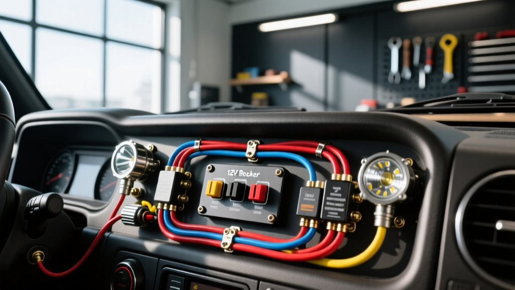
Introduction to Centralized Auxiliary Switching
Upgrading a truck or SUV with off-road light bars, winches, and onboard air compressors requires a reliable method of control. While individual toggle switches scattered across the dashboard were common in the past, a centralized 12v rocker switch panel provides a cleaner, safer, and more professional installation. However, simply plugging wires into the back of a switch panel is a recipe for melted wiring harnesses or electrical fires if the underlying circuit logic is flawed. This guide details the professional methodology for wiring a multi-gang rocker switch panel using automotive relays, proper AWG sizing, and fused power distribution blocks.
Understanding the 5-Pin SPST Rocker Switch Pinout
Most aftermarket marine and off-road switch panels utilize a standard 5-pin SPST (Single Pole, Single Throw) configuration with an integrated LED indicator. Before making any connections, you must understand the internal circuitry. The switch actually contains two separate circuits: the load-bearing switch mechanism and the low-draw LED illumination circuit.
- Pin 2 (Load Output): Connects to the relay coil (Pin 85). This sends the 12V trigger signal when the switch is flipped.
- Pin 3 (Power Source): Connects to a fused 12V source. This provides the power that flows through the switch to the relay coil.
- Pin 7 (Illumination +): Powers the internal LED backlight. Can be tied to Pin 3 (backlight turns on with switch) or a separate dash-dimmer circuit.
- Pin 8 (Illumination -): Ground for the internal LED backlight.
Expert Note: Some overseas manufacturers swap Pin 2 and Pin 3. Always verify continuity with a digital multimeter before applying power. Furthermore, never run high-draw loads (like a 240W LED light bar pulling 20A) directly through Pins 2 and 3. The internal copper contacts are typically rated for 10A to 20A maximum and will overheat. Always use the switch to trigger a Bosch-style automotive relay.
Tools and Materials Required
To meet SAE J1128 standards for low-tension primary automotive cable, you must use high-strand-count, pure copper wire (avoid CCA - Copper Clad Aluminum). Gather the following:
- Wire: 18 AWG (primary color-coded for switch triggers), 14 AWG or 12 AWG (for high-draw accessory power/ground).
- Terminals: 1/4-inch fully insulated female quick-disconnects for the switch pins; adhesive-lined heat shrink ring terminals for grounds.
- Crimper: A dedicated ratcheting crimper (e.g., IWISS IWS-3220M) to ensure gas-tight connections.
- Protection: Tesa 51036 PET cloth wiring tape and corrugated split loom for under-hood routing.
- Power Distribution: A marine-grade fused bus bar or fuse block (e.g., Blue Sea ST Blade).
Step-by-Step Installation Procedure
Step 1: Establish a Fused Power Distribution Point
Never daisy-chain multiple high-draw accessories directly to the battery positive terminal. Install a centralized fuse block near the battery. Run a heavy-gauge main power wire (4 AWG or 6 AWG, depending on total system draw) from the battery to the fuse block, placing a Mega Fuse or ANL fuse within 6 inches of the battery positive terminal. This ensures that if a short occurs, the main fuse blows before the wire melts.
Step 2: Wire the Switch Panel Triggers
Run an 18 AWG power wire from a switched 12V slot on your fuse block to Pin 3 on all switches in the panel. You can daisy-chain Pin 3 across the switches using jumper wires or a pre-made pigtail harness. Next, connect an 18 AWG wire from Pin 2 of each switch to Pin 85 (the relay trigger coil) of the corresponding accessory relay. This completes the low-amperage control circuit.
Step 3: Wire the High-Current Accessory Circuits
For the actual accessories (e.g., a 50-inch LED light bar), use 14 AWG or 12 AWG wire. Run power from a dedicated high-amp slot on the fuse block to Pin 30 on the relay. Connect Pin 87 on the relay to the positive terminal of the accessory. Finally, ground Pin 86 of the relay and the negative terminal of the accessory to the chassis.
Step 4: Master the Ground Connection
Over 80% of automotive electrical gremlins stem from poor grounds. Do not simply screw a ring terminal into painted sheet metal. Use a wire brush or sandpaper to remove paint and clear coat down to bare steel. Secure the ring terminal with a stainless steel screw and apply a dab of dielectric grease over the terminal to prevent oxidation.
Technical Reference Tables
Standard 5-Pin Bosch Relay Pinout
| Relay Pin | Wire Color (Standard) | Function | Connection Destination |
|---|---|---|---|
| 85 | Yellow | Coil Ground / Trigger | Switch Panel Pin 2 |
| 86 | Black | Coil Power / Ground | Chassis Ground or 12V Source |
| 30 | Red | Common Power Input | Fused 12V from Distribution Block |
| 87 | Blue | Normally Open (NO) Output | Accessory Positive (+) |
| 87a | White | Normally Closed (NC) | Not used for standard off-road lights |
AWG Wire Sizing for 12V DC Automotive Loads
The following chart is based on Blue Sea Systems wire sizing guidelines for a 3% voltage drop at 10 feet of total circuit length (positive and negative combined).
| Maximum Draw (Amps) | Recommended Wire Gauge (AWG) | Typical Fuse Size | Common Application |
|---|---|---|---|
| 10A | 16 AWG | 15A | Interior rock lights, relay triggers |
| 15A | 14 AWG | 20A | Small LED pods, onboard air solenoid |
| 20A | 12 AWG | 25A | 50-inch LED light bars, heated seats |
| 30A | 10 AWG | 35A | Winch solenoids, large inverters |
Troubleshooting Common Switch Panel Issues
The PWM Dimmer Flicker Effect
Symptom: When wiring Pin 7 (Illumination +) to a modern truck's headlight switch or dash dimmer circuit (common on 2015+ Ford F-150s and 2019+ Ram trucks), the rocker switch LED backlights strobe or flicker rapidly.
Cause: Modern vehicles use Pulse Width Modulation (PWM) to dim incandescent dash bulbs. The computer rapidly pulses the 12V signal on and off to simulate lower voltage. While incandescent bulbs have thermal lag and appear dim, LEDs react instantly, causing a visible strobe effect.
Fix: Do not use the OEM dimmer circuit for LED rocker switch illumination. Instead, wire Pin 7 to a clean, constant 12V switched source (such as an upfitter switch or an accessory fuse), and wire Pin 8 to ground. You will lose the ability to dim the switch backlights, but the flickering will be completely eliminated.
Relay Clicking but Accessory Fails to Power
Symptom: You hear the relay click when flipping the switch, but the off-road light bar does not turn on.
Cause: The control circuit (Pins 85/86) is functioning, but the high-current circuit (Pins 30/87) has a fault. This is usually caused by a blown main fuse, a poor chassis ground on the accessory itself, or severe voltage drop due to undersized wire.
Fix: Use a multimeter to test for 12V at Pin 30. If present, test for 12V at Pin 87 while the switch is engaged. If Pin 87 has 12V but the light remains off, the fault is in the wiring between the relay and the light, or the light's ground connection. Sand down the ground point and retest.