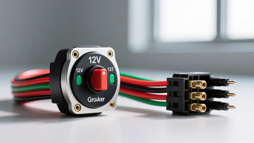
The Anatomy of a 12V Round Rocker Switch
When integrating aftermarket lighting, winches, onboard air compressors, or auxiliary fuel pumps, the 12V round rocker switch is a staple of custom automotive and marine dashboards. Whether you are utilizing a standard 28mm Carling V-Series or a generic 20mm mini-rocker, these switches provide a clean, water-resistant interface for controlling high-amperage circuits. However, improper wiring, overloading, and misunderstood pinout configurations frequently lead to melted housings, burnt-out LEDs, or total circuit failure.
Troubleshooting a 12V round rocker switch requires a systematic approach to isolate the fault between the power source, the switch contacts, the internal LED resistor network, and the downstream load. This guide provides a step-by-step diagnostic flow tailored specifically to the unique electrical characteristics of round automotive rocker switches.
The Critical Pinout Discrepancy: OEM vs. Generic
The most common cause of immediate failure or blown fuses when installing a 12V round rocker switch is assuming all 3-pin switches share the same internal architecture. There is a massive discrepancy between premium OEM switches (like those manufactured by Carling Technologies/Littelfuse) and generic import switches.
- Generic 3-Pin SPST (OFF-ON): Pin 1 is LED Ground, Pin 2 is 12V+ Source, Pin 3 is Load Output. If you apply 12V+ to Pin 1, you will short the circuit or destroy the internal LED resistor.
- Carling V-Series 3-Pin SPST (Dependent LED): Pin 2 is 12V+ Source, Pin 3 is Load Output, Pin 7 (often physically located on the opposite side) is LED Ground. Applying 12V+ to Pin 1 or Pin 7 on a Carling switch will result in a dead short.
Always verify your specific switch's pinout with a multimeter's continuity tester before applying 12V power.
Step-by-Step Troubleshooting Decision Tree
Use the following diagnostic matrix to isolate your specific failure mode. Ensure your multimeter is set to DC Volts (20V range) for live circuit testing, and Ohms/Continuity for dead-circuit testing.
Symptom A: Switch Actuates and Load Works, but LED Remains Dark
- Verify LED Ground Path: The internal LED requires a dedicated path to chassis ground. If using a generic 3-pin switch, probe Pin 1 with your multimeter's red lead while the black lead is on a known good chassis ground. You should read 0V. If you read 12V, your ground wire is broken or disconnected.
- Check for Blown Internal Resistor: If the ground is confirmed good, the internal current-limiting resistor for the LED has likely failed due to voltage spikes (common in off-road vehicles with high-output alternators lacking spike suppression). The switch contacts are still functional, but the switch must be replaced to restore the indicator light.
- Inspect for Polarity Reversal: Some generic switches use a standard diode instead of a current-limiting resistor. If wired with reverse polarity, the load may still engage (if it's a simple resistive load like a halogen light), but the LED will not illuminate.
Symptom B: LED Illuminates, but Load Does Not Engage
- Test Pin 3 (Load Output) Voltage: With the switch in the ON position, probe the Load terminal. You should read within 0.2V of your battery voltage (typically 12.4V - 12.8V). If you read 0V, the internal mechanical contacts have failed or carbon tracking has destroyed the contact pad.
- Perform a Voltage Drop Test Across the Switch: Place your red multimeter probe on the 12V+ Source terminal (Pin 2) and the black probe on the Load terminal (Pin 3). Actuate the switch. A healthy switch will show a voltage drop of less than 0.1V. If you read more than 0.5V, the internal contacts are pitted, corroded, or carbon-fouled, creating high resistance. Replace the switch immediately before it melts.
- Verify Downstream Ground: If the switch outputs a full 12V+ but the load (e.g., a relay coil or LED light bar) does not activate, the fault lies downstream. Check the load device's chassis ground for paint, rust, or loose ring terminals.
Symptom C: Switch Melts, Discolors, or Emits a Burning Odor
- Calculate the True Amperage Draw: Round rocker switches are typically rated for 10A to 20A at 12V DC. However, inductive loads (like air compressors, winch solenoids, or fuel pumps) experience a massive inrush current upon startup—often 3 to 5 times their running amperage. If your compressor draws 15A running, the 60A inrush will quickly weld the switch contacts together and melt the ABS/Nylon housing.
- Inspect Terminal Crimps: A loose 0.250-inch (6.3mm) quick-disconnect female spade terminal will create a high-resistance connection. According to Ohm's Law (P = I²R), this resistance generates intense localized heat. Ensure all terminals are crimped using a SAE J1128 compliant ratcheting crimper, not standard pliers.
- Solution - Integrate a Relay: Never run high-amperage inductive loads directly through a dashboard rocker switch. Use the rocker switch solely to trigger the 12V+ coil (Pin 86) of a 30A or 40A Bosch-style automotive relay. The relay coil draws less than 150mA, keeping the rocker switch completely cool.
Symptom D: LED Glows Dimly When Switch is in the OFF Position
This phenomenon, known as 'ghosting' or 'backfeed,' occurs when the switch's LED ground wire is incorrectly tied to the Load output wire instead of a dedicated chassis ground. When the switch is OFF, the LED attempts to find a path to ground through the downstream load device. If the load device has a parasitic ground path (such as a solid-state relay, a motor with a snubber diode, or an LED driver with internal capacitors), a micro-current will flow backward through the LED, causing a dim glow. Fix: Reroute the LED ground wire (Pin 1 or Pin 7) directly to a clean, bare-metal chassis ground point.
Wire Gauge and Terminal Specifications
Selecting the correct wire gauge and terminal size is critical for preventing voltage drop and thermal runaway. The following table outlines the specifications for 12V round rocker switch circuits based on Blue Sea Systems and SAE standards.
| Max Continuous Load | Recommended Wire Gauge (SAE GXL) | Terminal Width | Fuse Rating (ATC/ATO) |
|---|---|---|---|
| Up to 5A | 18 AWG | 0.187 in (4.8mm) | 7.5A |
| Up to 10A | 16 AWG | 0.187 in (4.8mm) | 15A |
| Up to 15A | 14 AWG | 0.250 in (6.3mm) | 20A |
| Up to 20A | 12 AWG | 0.250 in (6.3mm) | 25A |
| Relay Coil Trigger | 18 AWG | 0.187 in (4.8mm) | 3A - 5A |
Expert Tip: Always use adhesive-lined marine-grade heat shrink over your quick-disconnect crimps. Engine bay and under-dash environments are subject to extreme humidity and temperature cycling, which causes standard vinyl insulated crimps to wick moisture and corrode the copper strands, leading to high resistance.
Advanced Diagnostics: Verifying the Internal Contact Mechanism
If your multimeter indicates continuity across the source and load pins when the switch is ON, but the circuit still fails under load, you are likely dealing with 'carbon tracking.' When a switch is opened under a heavy load without a relay, an electrical arc forms across the separating contacts. Over time, this arc vaporizes the copper and silver plating, depositing a layer of carbon residue. Carbon is a poor conductor compared to copper, but it will pass the low-voltage test of a multimeter's continuity setting. However, under a real 10A load, the carbon layer acts as a resistor, causing a massive voltage drop.
To definitively test for carbon tracking without dismantling the switch, perform a loaded voltage drop test. Connect your load, turn the switch ON, and measure the voltage directly at the load's positive terminal. Then, measure the voltage at the switch's source terminal. If the voltage at the load is more than 0.5V lower than the voltage at the source, the switch contacts are degraded and the unit must be discarded.
References and Industry Standards
- Littelfuse / Carling Technologies V-Series Rocker Switch Datasheets - For OEM pinout matrices and mechanical torque specifications.
- SAE J1128 Standard - Specifications for low-tension primary automotive cable (GXL/TXL) insulation and thermal ratings.
- Blue Sea Systems DC Circuit Wire Sizing Guide - Authoritative reference for 12V marine and off-road voltage drop calculations.