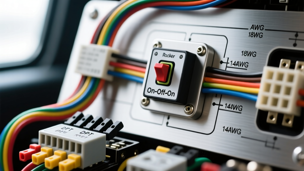
Understanding the Momentary On Off On Rocker Switch
In custom automotive electrical installations, selecting the correct actuator is just as critical as sizing your wire gauge. The momentary on off on rocker switch—often denoted in engineering schematics as (ON)-OFF-(ON)—is a specialized spring-return actuator. Unlike a maintained switch that locks into position, a momentary switch requires continuous physical pressure to keep the circuit closed. The instant you release the paddle, the internal spring mechanism forces the contacts back to the center 'OFF' state.
This fail-safe design is mandatory for high-risk or reversible automotive accessories. You will frequently find this switch type deployed in winch in/out controls, air suspension lift/lower manifolds, motorized tonneau covers, hydraulic dump beds, and locking differential actuators. If the operator lets go of the switch during a bind or emergency, the circuit instantly breaks, preventing catastrophic mechanical over-travel or electrical fires.
This complete wiring diagram walkthrough will dissect the internal mechanics of the 6-pin DPDT (Double Pole Double Throw) momentary configuration, provide a step-by-step polarity-reversing schematic, and detail the mandatory relay integration required for high-current inductive loads.
6-Pin DPDT vs. 3-Pin SPDT: Internal Pinout Configurations
Before cutting wire or crimping terminals, you must identify your exact switch topology. The market is flooded with both 3-pin SPDT (Single Pole Double Throw) and 6-pin DPDT variants. For any application requiring a reversible DC motor (such as a winch or power window), the 6-pin DPDT is the industry standard.
Standard 6-Pin DPDT (ON)-OFF-(ON) Pin Mapping
A standard 6-pin switch features two completely isolated internal circuits (poles), each with a common terminal and two throw terminals. The pins are typically numbered 1 through 6, arranged in two rows of three.
| Pin Number | Internal Designation | Function in Up Position (ON) | Function in Down Position (ON) |
|---|---|---|---|
| Pin 1 | Throw A1 | Connects to Pin 2 | Open |
| Pin 2 | Common A | Output to Load A | Output to Load A |
| Pin 3 | Throw A2 | Open | Connects to Pin 2 |
| Pin 4 | Throw B1 | Connects to Pin 5 | Open |
| Pin 5 | Common B | Output to Load B | Output to Load B |
| Pin 6 | Throw B2 | Open | Connects to Pin 5 |
Reference: For exact mechanical tolerances and contact resistance ratings, consult the Littelfuse Rocker Switch Datasheets.
Complete Wiring Diagram Walkthrough: Polarity Reversing Motor Control
The most common and complex use case for a momentary on off on rocker switch is reversing the polarity of a 12V DC motor. By crossing the power and ground feeds on the switch's throw terminals, you can dictate the direction of the motor based on which way the paddle is pressed. This walkthrough assumes a direct-drive, low-amperage motor (under 15A), such as a small actuator or electric valve. High-amperage loads require relay integration, detailed in the next section.
Step 1: The Jumper Wire Configuration
To achieve polarity reversal without a specialized reversing relay pack, you must install two jumper wires on the switch terminals. Using 12 AWG primary wire, create the following bridges:
- Jumper 1: Connect Pin 1 to Pin 6.
- Jumper 2: Connect Pin 3 to Pin 4.
Step 2: Power and Ground Feed Routing
Next, supply your main power and chassis ground to the jumpered pins.
- Main 12V+ Feed: Route a fused 12V+ line (Red wire, 12 AWG) from your accessory bus or battery directly to the Pin 1 / Pin 6 jumper bridge.
- Main Ground Feed: Route a dedicated chassis ground (Black wire, 12 AWG) directly to the Pin 3 / Pin 4 jumper bridge. Do not rely on daisy-chained grounds; use a dedicated ring terminal bolted to bare metal.
Step 3: Motor Output Connections
The common pins (2 and 5) will now serve as your alternating polarity outputs.
- Motor Lead A (Blue Wire): Connect to Pin 2.
- Motor Lead B (Yellow Wire): Connect to Pin 5.
Circuit Logic Verification
Let us trace the current flow to verify the schematic. When you press the switch UP, Pin 1 connects to Pin 2, sending 12V+ to Motor Lead A. Simultaneously, Pin 6 connects to Pin 5, connecting Motor Lead B to Ground. The motor spins forward. When you press the switch DOWN, Pin 3 connects to Pin 2, grounding Motor Lead A, while Pin 4 connects to Pin 5, sending 12V+ to Motor Lead B. The motor spins in reverse. Releasing the paddle springs the switch to the center OFF position, opening all circuits and dynamically braking the motor.
High-Current Relay Integration (Bosch ISO Mini)
A critical mistake made by novice installers is routing high-amperage loads directly through the rocker switch. Most standard marine and automotive rocker switches are rated for a maximum of 15A to 20A. However, the inrush current of a 12V winch solenoid, an air compressor, or a heavy linear actuator can easily exceed 40A. Passing this current through the switch's internal copper wipers will cause rapid thermal degradation, voltage drop, and eventually, a melted plastic housing.
To safely wire a momentary on off on rocker switch for high-current loads, you must use the switch solely as a low-amperage trigger mechanism for a pair of standard 5-pin Bosch-style ISO mini relays.
Dual Relay Reversing Schematic
- Switch Power Feed: Run an 18 AWG Red wire from a switched 12V ignition source to Pin 1 and Pin 6 (jumpered). This limits the switch to handling only the relay coil current (approx. 150mA per relay).
- Switch Ground Feed: Run an 18 AWG Black wire from a clean chassis ground to Pin 3 and Pin 4 (jumpered).
- Relay Coil Triggers: Connect Pin 2 to the 86 terminal on Relay A, and Pin 5 to the 86 terminal on Relay B.
- Relay Coil Grounds: Connect the 85 terminals on both Relay A and Relay B to a common chassis ground.
- High-Current Motor Routing: Connect 10 AWG Red wire from the battery (via a 40A mega fuse) to the 30 terminals on both relays. Connect the 87 terminal of Relay A to Motor Lead A, and the 87 terminal of Relay B to Motor Lead B. The 87a terminals remain unused.
For comprehensive relay load ratings and lifecycle expectations, refer to the Bosch Automotive Relays Application Guidelines.
Wire Sizing, Terminals, and SAE J1128 Standards
Automotive wiring is not a place for household hardware store supplies. All primary wire used in your momentary switch circuits must comply with SAE J1128 Low Tension Primary Cable standards. This ensures the copper stranding is optimized for DC current and the PVC or XLPE insulation can withstand under-hood temperatures up to 125°C (257°F) and exposure to battery acid, oil, and road salt.
AWG Sizing Chart for Custom Installs
| Circuit Type | Max Amperage | Recommended AWG | Wire Color Standard |
|---|---|---|---|
| Relay Coil Triggers (Switch to 86) | 2A - 5A | 18 AWG | Red (12V), Black (Gnd) |
| Low-Current Direct Motor Loads | 15A | 12 AWG | Blue / Yellow |
| High-Current Relay Feeds (30 to Load) | 30A - 40A | 10 AWG | Red |
Terminal Crimping and Flyback Protection
Never use pliers to crimp automotive spade terminals. You must use a ratcheting crimp tool calibrated for non-insulated or vinyl-insulated terminals to achieve a cold-weld gas-tight connection. Furthermore, when wiring relay coils, the sudden collapse of the electromagnetic field when you release the momentary switch sends a high-voltage spike (inductive kickback) backward through the circuit. Over time, this arcing will pit and destroy the internal copper contacts of your rocker switch. To prevent this, solder a 1N4007 flyback diode across the 85 and 86 terminals of your relays, with the silver stripe facing the 12V+ trigger side. This clamps the voltage spike and exponentially extends the lifespan of your switch.
Real-World Troubleshooting and Failure Modes
Even with a flawless schematic, environmental factors and poor execution can cause circuit failures. Use this decision tree to diagnose issues with your momentary on off on rocker switch installation.
| Symptom | Probable Cause | Diagnostic Fix |
|---|---|---|
| Motor hums but does not move in one direction | Voltage drop across a corroded switch terminal or loose crimp on the active throw pin. | Use a multimeter to measure voltage at Pin 2 and Pin 5 under load. Re-crimp terminals and apply dielectric grease. |
| Switch housing is hot to the touch | Exceeding the 20A continuous rating of the switch; internal contacts are acting as a resistor. | Immediately reroute the circuit through ISO mini relays. The switch should only trigger coil current. |
| LED indicators flicker with engine RPM | Alternator ripple voltage interfering with cheap, non-resistor LED rocker switches. | Install a 12V DC voltage regulator or upgrade to high-quality Carling V-Series switches with integrated solid-state LED drivers. |
| Switch springs back to OFF, but motor continues to run | Internal copper wipers have melted together or welded due to high-amp arcing. | Replace the switch immediately. Verify relay flyback diodes are installed to prevent future contact welding. |
By adhering strictly to these wiring diagrams, SAE wire standards, and relay integration protocols, your custom installation will remain reliable, safe, and immune to the harsh electrical environments inherent in modern vehicles.