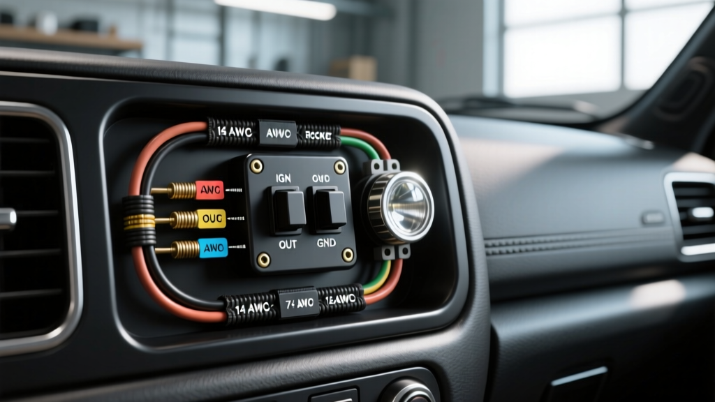
The Upgrade Project: Dual-Circuit Auxiliary Lighting
When outfitting a modern overland rig or daily-driven truck like a 2018-2023 Jeep Wrangler JL or a 2016-2023 Toyota Tacoma, dashboard real estate is at a premium. Factory auxiliary switch banks are often limited in amperage or locked behind complex CAN-bus programming. For enthusiasts running a dual-circuit lighting setup—such as a 50-inch white LED light bar for high-speed trail visibility and a pair of amber ditch lights for close-range dust or fog penetration—a three position rocker switch is the ultimate space-saving solution. By utilizing an ON-OFF-ON DPDT (Double Pole, Double Throw) configuration, you can control two distinct high-draw circuits from a single standard 1.45-inch cutout, eliminating the need for stacked switch pods and reducing dash clutter.
Anatomy of the 7-Pin Three Position Rocker Switch
The industry standard for automotive switch panels is the Contura V-Series 7-pin rocker. Unlike a simple SPST (Single Pole Single Throw) ON-OFF switch that merely breaks a single 12V line, the 7-pin three position rocker switch features independent output terminals and dedicated grounds for the internal upper and lower LED indicator lights. This allows the switch to route power to Circuit A when toggled up, Circuit B when toggled down, and kill both circuits in the center detent.
Standard 7-Pin Terminal Pinout
| Pin Number | Function | Connection Target |
|---|---|---|
| Pin 7 | 12V+ Power Input | Fused Ignition Source (14 AWG) |
| Pin 2 | Output 1 (Upper Position) | Relay 1 Trigger (Pin 86) |
| Pin 3 | Output 2 (Lower Position) | Relay 2 Trigger (Pin 86) |
| Pin 8 | Upper Indicator LED Ground | PWM Dimmer Circuit or Chassis Ground |
| Pin 1 | Lower Indicator LED Ground | PWM Dimmer Circuit or Chassis Ground |
| Pins 4, 5, 6 | Not Used / Internal Jumper | Leave Empty (Isolate with heat shrink) |
Component Selection and AWG Sizing
A critical mistake in aftermarket lighting upgrades is running the full accessory load directly through the switch contacts. A standard Contura switch is rated for 20A maximum. A 50-inch LED light bar can draw 14A-18A, and inrush current upon startup can spike higher, risking contact welding or melting the switch housing. According to the SAE J1128 Low Tension Primary Cable Standard, you must use automotive-grade cross-linked polyethylene (GXL or TXL) wire, which handles higher engine-bay temperatures than standard PVC wire.
Instead of routing the main load through the dash, the three position rocker switch will only handle the low-amperage trigger current (under 150mA) for a pair of ISO Mini 5-Pin Automotive Relays. The relays will handle the heavy 14 AWG current directly from the battery.
Required Materials & Hardware
- Switch: 7-Pin DPDT (ON-OFF-ON) Contura Rocker with laser-etched custom lenses.
- Relays: Two (2) ISO Mini 5-Pin SPDT Relays (Bosch-style, 40A rating).
- Wire (Power/Ground): 14 AWG SAE J1128 GXL (Red for 12V+, Black for Ground).
- Wire (Trigger/Illumination): 18 AWG GXL (Blue for Trigger 1, Yellow for Trigger 2, White for Illumination Ground).
- Connectors: Deutsch DT 2-pin receptacles for the light pigtails, ring terminals for chassis/battery grounds.
- Protection: 20A and 10A ATO blade fuses, adhesive-lined dual-wall heat shrink (3/16" and 1/4").
- Tools: Ratcheting open-barrel crimper, Deutsch pin insertion tool, heat gun, wire strippers.
Step-by-Step Wiring Guide: Dual-Circuit Light Bar
Follow this sequence to ensure clean routing, proper circuit isolation, and reliable termination. For comprehensive wiring schematics on specific off-road light brands, refer to the Rigid Industries Wiring Diagrams & Tech library.
Step 1: Establish the High-Current Power Feeds
Run a length of 14 AWG Red wire from the positive battery terminal to a centralized relay block mounted in the engine bay. Install a 30A ATO fuse holder within 6 inches of the battery terminal to protect the main feed. From the relay block, split the 12V+ feed into the Pin 30 terminals of both Relay 1 (White Lights) and Relay 2 (Amber Lights). Ground the relay block to the chassis using 14 AWG Black wire and a star-washer ring terminal, ensuring you scrape away any powder coating or paint to achieve bare-metal contact.
Step 2: Route the Switch Trigger Wires
Feed two 18 AWG wires (Blue and Yellow) from the engine bay relay block through the firewall grommet into the cabin. Terminate these wires into the Pin 86 trigger terminals on Relay 1 and Relay 2, respectively. Use adhesive-lined heat shrink over the open-barrel crimps to prevent moisture wicking into the relay coil.
Step 3: Terminate the 7-Pin Three Position Rocker Switch
At the dashboard, connect the wires to the switch terminals as follows:
- Pin 7: Connect to a 12V+ Ignition-switched source (use an Add-A-Fuse on a 10A ignition circuit like the 12V accessory socket). Use 14 AWG Red wire.
- Pin 2: Connect the 18 AWG Blue wire (Triggers Relay 1 / White Light Bar).
- Pin 3: Connect the 18 AWG Yellow wire (Triggers Relay 2 / Amber Ditch Lights).
- Pins 4, 5, 6: Leave empty. Cap any exposed wire ends if using a pre-pigtailed harness.
Step 4: Wire the Load Side (Relay to Lights)
From Pin 87 (Normally Open) on Relay 1, run 14 AWG Red wire to the positive pin of the Deutsch DT connector for the white light bar. From Pin 87 on Relay 2, run 14 AWG Red wire to the amber ditch lights. Ensure the main ground wires for the lights are secured to the chassis or tied back to the battery negative terminal using 14 AWG Black wire. Note: Pin 87a (Normally Closed) is unused in this application and should be bent back or insulated to prevent accidental shorting.
Dash Illumination and PWM Dimmer Integration
The upper and lower indicator LEDs inside the rocker switch (Pins 8 and 1) require a ground path to illuminate. In older vehicles, you could simply ground these to the chassis. However, modern vehicles (2015+) use Pulse Width Modulation (PWM) dimmer circuits for interior lighting. Connecting the switch illumination directly to a PWM circuit can cause the switch LEDs to flicker or throw a BCM (Body Control Module) fault code due to the inductive load of the LEDs.
The Expert Fix: To integrate with the factory dash dimmer without triggering CAN-bus errors, install a 1N4001 rectifier diode in-line on the 18 AWG White illumination ground wire. Solder the diode with the silver band facing away from the switch (towards the vehicle's dimmer circuit). This allows the ground signal to pass through but blocks any voltage backfeed from the BCM when the PWM cycle switches high. Connect Pins 8 and 1 together using a jumper wire, then route them through the diode to the factory dimmer ground wire (often a White/Black tracer wire on Toyota, or a Purple/White tracer on Jeep/Chrysler).
Expert Modification: The Diode Bypass (ON-ON-ON Logic)
The standard ON-OFF-ON switch isolates Circuit 1 and Circuit 2. If your modification project requires running the Amber Ditch lights simultaneously with the White Light Bar when toggled down, you can modify the switch logic without buying a new component. Solder a 1N5408 (3A) heavy-duty diode between Pin 2 and Pin 3, with the anode connected to Pin 3 and the cathode connected to Pin 2. When you toggle the switch down (energizing Pin 3), current will flow through the diode to Pin 2, triggering both relays simultaneously. When toggled up (energizing Pin 2), the diode blocks reverse current, keeping only the White Light Bar active.
Troubleshooting Common Installation Faults
Even with meticulous planning, custom wiring projects can present issues during the testing phase. Use this decision tree to diagnose faults rapidly.
| Symptom | Probable Cause | Diagnostic Fix |
|---|---|---|
| Switch toggles, but relay clicks and lights do not turn on. | Voltage drop on Pin 30 (Main Power) or poor chassis ground on the light circuit. | Use a multimeter to test Pin 87 output under load. Check for paint under the light's ground ring terminal. |
| Relay clicks rapidly (chattering) when toggled. | Undersized trigger wire or high resistance on the ignition feed to Pin 7. | Verify Pin 7 is on a dedicated ignition circuit, not a shared CAN-bus sleep circuit. Upgrade trigger to 16 AWG. |
| Switch indicator LEDs flicker wildly or stay on when vehicle is off. | PWM backfeed or incorrect diode orientation on the illumination ground. | Verify the 1N4001 diode silver band is facing the vehicle harness. Check for parasitic draw with an ammeter. |
| White lights turn on, but Amber lights do not (or vice versa). | Swapped trigger wires on Pin 2 and Pin 3, or blown ATO fuse on the specific relay circuit. | Test continuity from switch output pins to relay Pin 86. Swap the 10A/20A fuses to rule out a blown element. |
By adhering to SAE wire standards, utilizing relays to protect the switch contacts, and properly managing dash illumination grounds, your three position rocker switch upgrade will provide reliable, factory-grade control over your auxiliary lighting modification project for years to come.