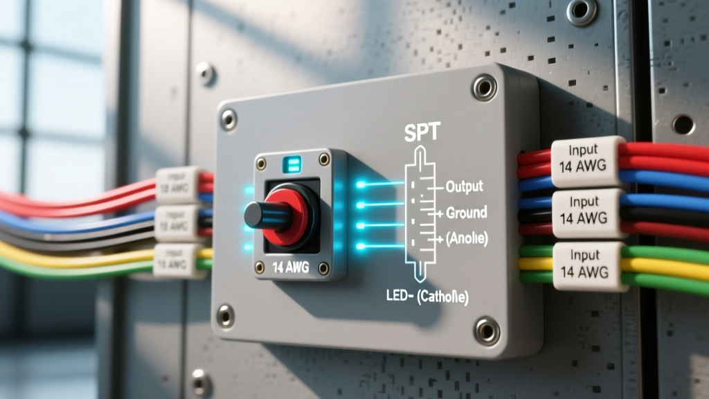
Introduction to 5-Pin SPST Illuminated Rocker Switches
When integrating auxiliary lighting, winches, onboard air compressors, or custom CAN-bus monitoring systems into a 12V automotive electrical architecture, the 5-pin Single Pole Single Throw (SPST) illuminated rocker switch remains the definitive industry standard. Often modeled after the Carling V-Series contour architecture, these switches provide a robust, splash-proof (IP65 to IP68 rated when properly capped) interface for high-current loads. However, improper rocker switch with light wiring is a leading cause of parasitic battery drain, melted switch housings, and backfeed errors in modern multiplexed vehicle networks.
This technical specification reference details the exact terminal pinouts, wire gauge requirements, LED illumination logic, and relay integration protocols required for reliable, marine-grade, and off-road automotive installations. Understanding the internal brass wiper contacts and independent LED circuits is critical for preventing thermal runaway and ensuring long-term switch longevity.
Standard 5-Pin Terminal Pinout Specifications
The ubiquitous 5-pin SPST rocker switch utilizes a standardized numbered terminal layout stamped directly into the rear nylon or polycarbonate housing. Unlike simple 2-pin toggle switches, the 5-pin variant separates the main load-bearing circuit from the low-current LED illumination circuits, allowing for complex dash-integration logic.
| Terminal Pin | Standard Function | Wire Color Code | Circuit Type | Max Continuous Current |
|---|---|---|---|---|
| Pin 2 | Common Ground | Black | LED Illumination Return | 500mA (LED Draw) |
| Pin 3 | Power In (Line) | Red | Main 12V+ Source (Fused) | 20A (via internal contacts) |
| Pin 5 | Power Out (Load) | Blue | Switched 12V+ Output | 20A (via internal contacts) |
| Pin 6 | Illumination In (Upper) | Yellow / White | 12V+ Dash/Accessory Feed | 20mA (Upper LED) |
| Pin 8 | Illumination In (Lower) | Green / Orange | 12V+ Load-Side Feed | 20mA (Lower LED) |
Terminal Identification and Logic Flow
Pin 2 (Ground): This terminal provides the common ground path for both internal LEDs. It must be tied to a clean, dedicated chassis ground or a fused ground bus bar. Sharing this ground with high-draw accessories (like fuel pumps or cooling fans) will induce voltage fluctuations, causing the switch LEDs to flicker or dim erratically.
Pin 3 (Power In): The primary 12V+ feed. In a properly engineered system, this pin receives power from a fused distribution block or a master relay bus. It should never be wired directly to the battery without an inline ATC/ATO fuse rated appropriately for the downstream wire gauge.
Pin 5 (Power Out): The switched output. When the actuator is depressed, the internal silver-alloy wiper bridges Pin 3 and Pin 5. For loads exceeding 10A continuous, Pin 5 should only be used to trigger a relay coil, not to carry the primary accessory load.
Wire Gauge (AWG) and Current Rating Matrices
Selecting the correct American Wire Gauge (AWG) is dictated by SAE J1128 standards for low-tension primary automotive cable, factoring in ambient under-hood temperatures and voltage drop over distance. Using undersized wire on the switch legs leads to resistive heating, which transfers directly into the switch housing and degrades the internal polycarbonate actuator.
| Circuit Segment | Recommended AWG | Max Run Length (12V) | Inline Fuse Rating | Insulation Type |
|---|---|---|---|---|
| Pin 3 (Main Feed) | 14 AWG | 10 ft (3.0m) | 15A ATC | TXL / GXL (High Temp) |
| Pin 5 (Relay Trigger) | 18 AWG | 15 ft (4.5m) | 3A AGC Glass | TXL / GXL |
| Pins 2, 6, 8 (LED Legs) | 20 AWG - 18 AWG | 10 ft (3.0m) | 5A ATC (Shared bus) | PVC / TXL |
| Direct Load (No Relay) | 12 AWG - 10 AWG | 8 ft (2.4m) | 20A ATC | TXL / Cross-linked |
Expert Note: For engine bay installations where ambient temperatures exceed 105°C (221°F), standard PVC wire insulation will become brittle and crack. Always specify TXL (Thin-wall cross-linked) or GXL wire for Pin 3 and Pin 5 runs routed near exhaust manifolds or engine blocks.
LED Illumination Circuit Architecture
The dual-LED design of the 5-pin rocker switch allows installers to mimic OEM dashboard lighting behaviors. The upper LED (Pin 6) and lower LED (Pin 8) operate on completely independent circuits, sharing only the common ground at Pin 2.
Upper vs. Lower LED Logic Integration
- Upper LED (Pin 6 - Dash Dependent): Wire Pin 6 to an OEM accessory circuit (e.g., headlight switch illumination feed or Terminal 15 ignition-switched power). This ensures the upper symbol illuminates only when the vehicle's parking lights or ignition are active, preventing night-time glare and parasitic drain.
- Lower LED (Pin 8 - Load Dependent): Wire Pin 8 to the load side of your relay (Relay Pin 87) or directly to the accessory's positive trigger. The lower indicator bar will only illuminate when the switch is turned ON and the accessory is actively receiving power. If the accessory blows a fuse or the relay fails, the lower LED will remain dark, providing immediate visual fault feedback to the driver.
CAN-Bus and PWM Warning: Modern vehicles (2015+ GM, Ford, and FCA/Stellantis platforms) often use Pulse Width Modulation (PWM) for dashboard dimming circuits. If you wire Pin 6 to a PWM-controlled dash light feed, the switch's internal LED will strobe or buzz. To resolve this, install a 12V DC-to-DC PWM filter or tap a non-dimming accessory circuit (like the radio harness accessory wire) for Pin 6.
Relay Integration for High-Draw Accessories
While the internal contacts of a premium 5-pin rocker switch are rated for 20A at 12V DC, continuous high-amperage loads (such as 50-inch LED light bars drawing 18A, or air compressors with high inrush currents) will cause arcing across the brass wiper. This arcing pits the metal, increases resistance, and ultimately melts the switch. For any load exceeding 10A continuous, a standard Bosch-style 4-pin Mini ISO Relay must be utilized.
Standard 4-Pin Bosch Relay Wiring with Rocker Switch
- Relay Pin 30 (Common): Connect to fused 12V+ battery source (Main accessory power).
- Relay Pin 87 (Normally Open): Connect to the positive terminal of the accessory/load.
- Relay Pin 85 (Coil Ground): Connect to a clean chassis ground.
- Relay Pin 86 (Coil Power): Connect to Switch Pin 5 (Switched Output).
Flyback Diode Protection: When the rocker switch is turned off, the collapsing magnetic field in the relay coil generates a high-voltage inductive spike (back-EMF) that travels backward through Switch Pin 5. In vehicles with sensitive Body Control Modules (BCMs) or solid-state switching modules, this spike can trigger check-engine lights or fry the OEM control board. Solder a 1N4001 rectifier diode across Relay Pins 85 and 86 (diode stripe facing Pin 86) to safely dissipate this voltage spike.
Crimping and Terminal Retention Specifications
The 5-pin rocker switch utilizes standard 6.35mm (1/4-inch) male spade terminals. The mating female Quick Disconnect (QD) terminals must be crimped using a precision ratcheting crimper (e.g., IWISS SN-48B or equivalent open-barrel crimper) to ensure optimal electrical conductivity and mechanical retention.
According to USCAR-2 and SAE standards, a properly crimped 18 AWG terminal on a 6.35mm spade must withstand a minimum pull-out force of 15 lbs (66 N) without slipping. Always utilize 3:1 adhesive-lined marine heat shrink over the crimp barrel. The internal adhesive melts and seals the wire strands, preventing capillary action from drawing moisture and road salt into the switch housing, which is a primary cause of Pin 2 ground corrosion.
Troubleshooting Voltage Drop and LED Backfeed
Even experienced installers encounter anomalies when executing complex rocker switch with light wiring configurations. Below is a diagnostic matrix for common installation faults:
| Symptom | Probable Root Cause | Technical Resolution |
|---|---|---|
| Upper LED remains lit when vehicle is off. | Pin 6 wired to Terminal 30 (Constant 12V) instead of Terminal 15 (Ignition/Accessory). | Reroute Pin 6 to a verified ignition-switched or headlight-switched fuse tap. |
| Switch housing is hot to the touch; actuator feels sticky. | Thermal runaway. Load exceeds 15A continuous without a relay, causing internal contact resistance. | Immediately replace switch. Install a 4-pin relay and use Switch Pin 5 solely for the <3A relay coil trigger. |
| Lower LED (Pin 8) illuminates dimly when switch is OFF. | Inductive backfeed or shared ground floating voltage on the load circuit. | Ensure Pin 8 is wired to the load side of the relay. Add a bleed resistor (10k Ohm) across the load if necessary. |
| LEDs flicker rapidly at idle. | Pin 2 (Ground) is sharing a ground stud with a high-draw accessory (e.g., radiator fan). | Run a dedicated 18 AWG ground wire from Pin 2 directly to the negative battery terminal or a dedicated zero-volt bus bar. |
By adhering strictly to these pinout configurations, AWG matrices, and relay isolation protocols, you ensure that your custom auxiliary switch panels operate with OEM-level reliability, safety, and diagnostic clarity.