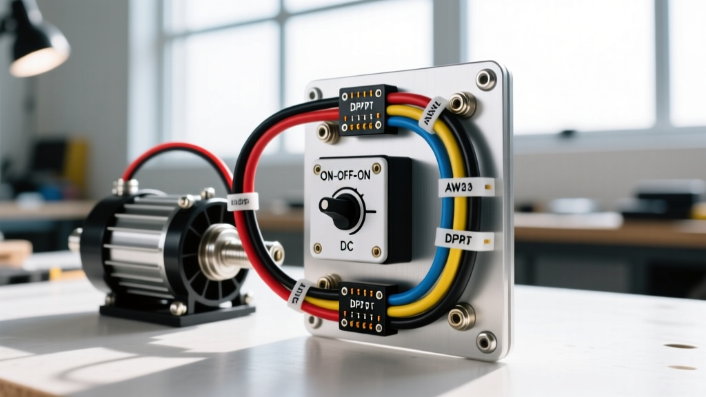
Introduction to the 3 Position Rocker Switch ON-OFF-ON
When designing custom automotive electrical systems for reversible accessories—such as winches, linear actuators, power antennas, or custom motorized liftgates—the 3 position rocker switch ON-OFF-ON is the industry standard control interface. Unlike standard single-pole ON-OFF switches that merely interrupt power, the ON-OFF-ON configuration allows operators to control the direction of a DC motor by reversing polarity, with a crucial center 'OFF' state that prevents accidental engagement and allows the motor to coast to a stop.
In automotive applications, these switches are typically Double Pole, Double Throw (DPDT) units featuring six electrical terminals. Selecting the correct wiring topology depends entirely on the amperage draw of your accessory. While a direct-wire setup is sufficient for low-draw actuators, high-current loads like off-road winches require the switch to act as a low-amperage trigger for heavy-duty solenoids or relays. This guide details the exact pinout mechanics, wire sizing standards per SAE J1128, and step-by-step wiring procedures for both low and high-current configurations.
Understanding the DPDT 6-Pin Configuration
To wire a 3 position rocker switch ON-OFF-ON correctly, you must understand its internal continuity matrix. A standard DPDT automotive rocker switch (such as the popular Carling V-Series) features six spade terminals on the rear housing. These are typically arranged in two rows of three.
Pinout Numbering and Internal Mechanics
For standardization, we will number the pins 1 through 6. Looking at the back of the switch with the terminals facing you:
- Top Row: Pin 1 (Left), Pin 2 (Center), Pin 3 (Right)
- Bottom Row: Pin 4 (Left), Pin 5 (Center), Pin 6 (Right)
| Switch Position | Internal Connection (Top Row) | Internal Connection (Bottom Row) | Circuit State |
|---|---|---|---|
| UP (ON 1) | Pin 2 connects to Pin 1 | Pin 5 connects to Pin 4 | Forward Polarity |
| CENTER (OFF) | No Connection | No Connection | Open Circuit (Coast) |
| DOWN (ON 2) | Pin 2 connects to Pin 3 | Pin 5 connects to Pin 6 | Reverse Polarity |
The center pins (2 and 5) serve as the common inputs for your power and ground sources, while the outer pins (1, 3, 4, and 6) act as the switched outputs to the load. By crossing the outputs, we achieve the polarity reversal required to change the motor's direction.
Direct Wiring Guide: Low-Current Actuators (< 15 Amps)
If you are wiring a low-draw accessory like a custom motorized dashboard vent or a small 12V linear actuator (drawing under 15A), you can wire the switch directly in-line without relays. This requires creating a polarity-reversing 'X' crossover on the back of the switch.
Required Materials
- DPDT 3 Position Rocker Switch ON-OFF-ON (20A rated minimum)
- 14 AWG SAE J1128 Primary Wire (Red for +12V, Black for Ground, Blue/White for Motor Legs)
- 14 AWG Fully Insulated Female Spade Disconnects
- Marine-Grade Adhesive-Lined Heat Shrink Tubing
Step 1: Create the Polarity Reversing Jumpers
To reverse the motor's direction, the positive and negative feeds must swap legs depending on the switch position. Cut two short lengths of 14 AWG wire to serve as jumper bridges.
- Install a female spade connector on both ends of the first jumper. Connect this jumper diagonally from Pin 1 to Pin 6.
- Install connectors on the second jumper. Connect this jumper diagonally from Pin 3 to Pin 4.
- This 'X' pattern ensures that the power source is always routed to one side of the motor while the ground is routed to the other, swapping seamlessly when the switch is toggled.
Step 2: Connect Power, Ground, and Load
- Power Input: Connect your fused +12V source (from the vehicle's ignition or battery bus) to Pin 2.
- Ground Input: Connect your chassis ground or battery negative to Pin 5.
- Motor Leg A: Connect a wire from the Pin 1 / Pin 6 junction to Terminal 1 on your DC motor.
- Motor Leg B: Connect a wire from the Pin 3 / Pin 4 junction to Terminal 2 on your DC motor.
Expert Tip: DC motors generate significant back-EMF (electromotive force) voltage spikes when the switch is snapped to the OFF position while the motor is spinning. To prevent internal arcing that will prematurely destroy the switch contacts, solder a bidirectional TVS (Transient Voltage Suppression) diode directly across the motor's two terminals.
High-Current Relay Setup: Winches and Heavy Motors (> 20 Amps)
Automotive winches and heavy liftgate motors can draw 50 to 150+ Amps under load. Running this current through a dashboard rocker switch will melt the housing and cause a severe fire hazard. For these applications, the 3 position rocker switch ON-OFF-ON is used solely as a low-current signal trigger for a heavy-duty solenoid contactor pack (like those used by Warn Industries) or dual high-amperage SPDT relays.
Wiring a 4-Post Winch Solenoid Pack
A standard off-road winch solenoid pack features four large threaded posts. Two are for the main battery/motor connections, and two are for the low-current switch triggers.
- Main Power Routing: Run 2 AWG welding cable from the vehicle's battery positive terminal to Solenoid Post A. Run 2 AWG from Solenoid Post B to Motor Terminal 1. Run 2 AWG from Motor Terminal 2 to Solenoid Post C. Finally, run 2 AWG from Solenoid Post D to a dedicated chassis ground or battery negative.
- Trigger Source: Run a fused 16 AWG +12V ignition-switched wire to Pin 2 on the rocker switch.
- Ground Source: Run a 16 AWG ground wire to Pin 5 on the rocker switch.
- Forward Trigger: Connect a wire from the Pin 1 / Pin 6 junction to the small trigger post on the 'Forward' solenoid.
- Reverse Trigger: Connect a wire from the Pin 3 / Pin 4 junction to the small trigger post on the 'Reverse' solenoid.
When the switch is toggled UP, Pin 2 connects to Pin 1, grounding the forward solenoid coil and engaging the winch. Toggling DOWN grounds the reverse solenoid. The center OFF position breaks the ground path for both coils, safely disengaging the motor.
Wire Sizing and Voltage Drop Specifications
Adhering to proper AWG sizing is critical to prevent voltage drop, which causes motors to run hot, lose torque, and fail prematurely. The following table outlines minimum wire gauges based on maximum continuous amperage and circuit length (round-trip distance from battery to load and back).
| Max Amperage | Under 10 ft Round Trip | 10 - 20 ft Round Trip | 20 - 30 ft Round Trip |
|---|---|---|---|
| 10A - 15A (Actuators) | 14 AWG | 12 AWG | 10 AWG |
| 20A - 30A (Relay Feeds) | 10 AWG | 8 AWG | 6 AWG |
| 50A - 80A (Small Winches) | 4 AWG | 2 AWG | 1/0 AWG |
| 100A+ (Heavy Winches) | 1/0 AWG | 2/0 AWG | 3/0 AWG |
Note: Always install a mega-fuse or ANL fuse within 18 inches of the battery positive terminal on the main power feed to protect the wiring harness in the event of a dead short.
Troubleshooting Common Installation Failures
Even with a flawless wiring diagram, environmental factors and component wear can cause operational issues. Use this diagnostic tree to resolve common faults with your 3 position rocker switch ON-OFF-ON installation.
- Symptom: Switch housing is hot to the touch or smells like melting plastic.
- Cause: The switch is carrying more current than its rated capacity, or the spade terminals are loose, creating high resistance and localized heat.
- Fix: Verify the amperage draw with an inductive clamp meter. If drawing over 15A continuously, upgrade to a relay/solenoid topology. Ensure all spade connectors are crimped with a proper ratcheting crimper, not pliers.
- Symptom: Motor runs in one direction, but stops or clicks when switched to the opposite direction.
- Cause: A broken crossover jumper wire, or a failed ground connection on the solenoid pack.
- Fix: Use a digital multimeter (DMM) to test for continuity across the diagonal jumpers (Pin 1 to 6, Pin 3 to 4) with the switch removed from the circuit. Inspect the vehicle chassis ground point for rust or paint interference.
- Symptom: Visible sparking inside the switch when toggled to OFF.
- Cause: Inductive kickback (back-EMF) from the DC motor arcing across the internal copper contacts.
- Fix: Install an RC snubber network or a bidirectional TVS diode across the motor terminals to absorb the voltage spike before it reaches the switch.
Authoritative References
For further engineering data on automotive wiring standards and switch tolerances, consult the following resources:
- SAE International - SAE J1128: Low Tension Primary Cable Standard
- Carling Technologies - V-Series Contura Rocker Switch Datasheets
- Littelfuse - Automotive Relay Application Guidelines & Wiring Topologies