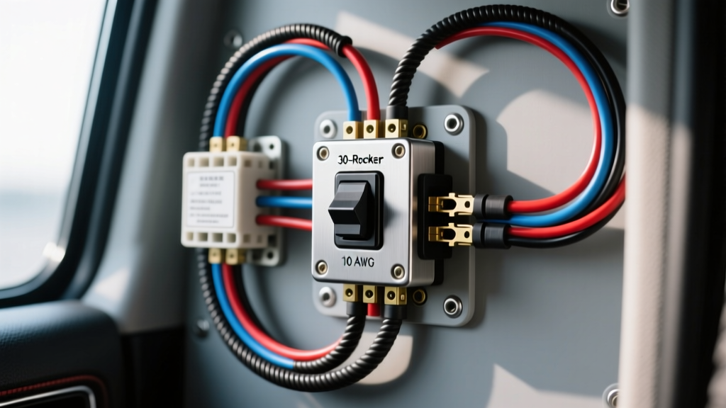
The Physics of a 30 Amp Rocker Switch: Contact Arcing and Thermal Limits
When outfitting a custom off-road rig, marine vessel, or heavy-duty truck with high-draw accessories, the 30 amp rocker switch is a ubiquitous component. However, a fundamental misunderstanding of electrical engineering principles leads many installers to wire these switches directly to heavy loads. In an advanced custom installation, treating a switch as a simple mechanical bridge is a recipe for thermal runaway, carbon tracking, and catastrophic harness failure.
According to the SAE J2298 standard for automotive switches, current ratings are heavily dependent on the load type (resistive vs. inductive) and the ambient operating temperature. A switch stamped with '30A' is typically rated for a peak resistive load under ideal bench conditions. In the real world, where under-hood temperatures exceed 80°C (176°F) and accessories draw heavy inductive currents, the continuous safe operating limit of a standard 1/4-inch spade terminal switch drops significantly.
The Inductive Kickback Phenomenon
Accessories like air compressors, winch solenoids, and high-output fuel pumps feature electric motors or heavy coils. These are inductive loads. When a 30 amp rocker switch interrupts an inductive circuit, the collapsing magnetic field generates a massive reverse voltage spike—often exceeding 100 volts for a fraction of a millisecond. This causes severe DC arcing across the internal copper contacts. Over time, this arcing vaporizes the contact surface, creating carbon deposits that increase resistance, generate excessive heat, and eventually melt the nylon switch housing.
PWM Dimming Incompatibility
A modern trend in custom lighting is the use of Pulse Width Modulation (PWM) dimmers integrated into the accessory circuit. If you attempt to route a 30A PWM signal directly through a standard mechanical rocker switch, the high-frequency switching (often 500Hz to 2kHz) will cause micro-arcing on every single pulse. Mechanical switches are entirely incompatible with PWM load-bearing. The switch must only handle the low-current logic signal for the PWM controller, while the controller handles the high-frequency switching of the main power.
ISO 7588 Relay Integration Architecture
To engineer a reliable 30 amp rocker switch circuit, the switch must be demoted from a 'load-bearing' role to a 'logic-trigger' role. By utilizing a standard ISO 7588 (Bosch-style) 5-pin 40A relay, the rocker switch only carries the coil current (typically 150mA to 200mA), entirely eliminating internal arcing and voltage drop across the switch contacts. For authoritative relay specifications, refer to Littelfuse Automotive Relays datasheets.
5-Pin Relay Pinout and Wiring Sequence
Use 10 AWG primary power wire and 16 AWG trigger wire for the following architecture:
- Pin 30 (Common Input): Connect directly to the battery positive terminal via an inline MAXI fuse (rated at 35A or 40A). Use 8 AWG wire if the run exceeds 10 feet.
- Pin 87 (Normally Open Output): Connect to the positive terminal of the accessory load. This wire carries the full 30A continuous load.
- Pin 85 (Coil Ground): Connect to a clean, bare-metal chassis ground. Use a ring terminal with a star washer to bite through the paint and e-coat.
- Pin 86 (Coil Trigger): Connect to the output terminal of your 30 amp rocker switch.
- Rocker Switch Input: Feed from an ignition-switched 12V source (e.g., fuse panel add-a-circuit) using 16 AWG wire. This ensures the accessory cannot be left on when the vehicle is parked.
Conductor Sizing and Voltage Drop Calculations
Wire gauge selection is not based solely on the fuse size; it is dictated by the total round-trip circuit length and acceptable voltage drop. For high-draw accessories like light bars or compressors, a voltage drop exceeding 3% (0.36V on a 12V system) will result in poor performance and premature motor failure. The ABYC E-11 Standard for marine DC wiring provides the most rigorous guidelines for voltage drop in harsh environments, which translates perfectly to high-end off-road builds.
| Wire Gauge (AWG) | Max One-Way Length (3% Drop @ 30A) | Resistance per 1000 ft | Recommended Application |
|---|---|---|---|
| 10 AWG | 9.5 Feet | 0.9989 Ohms | Short relay-to-load runs (e.g., hood-mounted lights) |
| 8 AWG | 15.2 Feet | 0.6282 Ohms | Standard roof rack light bar or cabin compressor |
| 6 AWG | 24.1 Feet | 0.3951 Ohms | Long runs to rear bumpers, winches, or marine transoms |
Note: Always calculate using the round-trip distance (Source to Load and back to Ground). If your battery is 5 feet from the load, the one-way length is 5 feet, but the total wire length is 10 feet.
Terminal Crimping and Environmental Sealing
The most common point of failure in a 30 amp rocker switch setup is the termination at the switch's 1/4-inch (6.35mm) spade terminals. Standard vinyl-insulated quick disconnects are insufficient for high-vibration, high-moisture environments.
Advanced Termination Protocol
- Strip and Inspect: Strip 16 AWG trigger wire to exactly 5/16 inch. Ensure no copper strands are nicked or severed.
- Terminal Selection: Use nylon-insulated (high-temperature rated) female quick disconnects. Avoid vinyl, which becomes brittle and shrinks under engine bay heat.
- Ratcheting Crimp: Use a precision ratcheting crimper calibrated for 16-14 AWG insulated terminals. The crimp must deform the terminal barrel in a 'W' or 'B' shape, ensuring a gas-tight cold weld between the copper strands and the brass terminal.
- Adhesive Heat Shrink: Slide a piece of 3M dual-wall, adhesive-lined heat shrink over the terminal before crimping. After crimping, apply heat until the terminal shrinks and a bead of hot-melt adhesive extrudes from the end. This prevents galvanic corrosion and moisture wicking into the wire strands.
Troubleshooting Decision Tree: Thermal and Voltage Failures
When a custom accessory circuit fails or behaves erratically, use this diagnostic tree to isolate the root cause without resorting to guesswork.
Symptom: Rocker Switch Housing is Hot to the Touch or Melting
- Cause A: Switch is wired directly to the load (no relay) and is carrying 30A continuous.
- Fix: Rewire circuit to use switch as a low-current relay trigger.
- Cause B: High resistance at the spade terminal due to a poor crimp or oxidized brass.
- Fix: Cut off old terminal, clean switch blade with contact cleaner, and apply a new gas-tight ratcheted crimp.
Symptom: Accessory Operates Weakly or Lights Dim Upon Activation
- Cause A: Severe voltage drop due to undersized ground wire or poor chassis ground location.
- Fix: Measure voltage drop across the ground circuit while under load. If >0.1V, relocate ground to bare structural steel and upgrade ground wire to match positive wire gauge.
- Cause B: Relay contacts are pitted from previous inductive arcing.
- Fix: Replace the ISO relay and install a flyback diode (e.g., 1N5408) across the load terminals to suppress future inductive spikes.
Symptom: Switch Illumination Flickers or Blows Vehicle ECU Fuses
- Cause: The internal LED/resistor network in cheap rocker switches is poorly isolated from the main power circuit, causing back-feed or PWM interference.
- Fix: Upgrade to a marine-grade, IP68-sealed rocker switch (such as Carling V-Series) with isolated LED illumination circuits, ensuring the switch ground pin (Pin 7 on standard DPST switches) is grounded independently from the load ground.
Final Engineering Validation
A properly engineered 30 amp rocker switch circuit relies on the principle of load separation. By utilizing the switch strictly for logic-level relay actuation, sizing conductors based on round-trip voltage drop mathematics, and executing gas-tight, environmentally sealed terminations, you create an electrical system that meets or exceeds OEM automotive standards. Never trust the stamped rating on a plastic housing; trust the physics of the circuit you design.