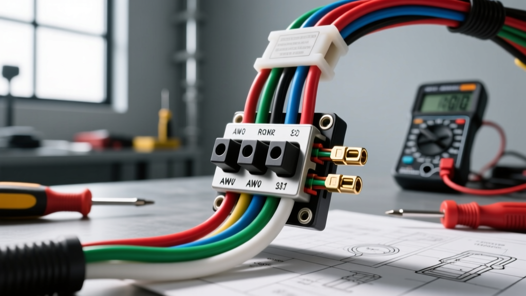
Understanding the 3-Pin Automotive Rocker Switch Anatomy
When integrating aftermarket 12V DC accessories—such as off-road light bars, winch controls, or auxiliary air compressors—the three pin rocker switch is the industry standard for user interface. Typically configured as a Single Pole Single Throw (SPST) switch with an integrated LED indicator, this component manages both the primary load circuit and the visual confirmation circuit. However, improper wiring, voltage drop, or incorrect pin identification frequently leads to accessory failure, blown fuses, or parasitic draws.
Before diving into the troubleshooting flow, it is critical to verify the pinout. While variations exist, the standard Carling Technologies Contura II / V-Series 3-pin configuration dominates the automotive and marine markets.
| Pin Number | Function | Standard Wire Color | Multimeter Test (Switch ON) |
|---|---|---|---|
| Pin 1 | 12V Power In (Source) | Red | 12.2V - 14.4V DC to Ground |
| Pin 2 | Load Out (To Accessory) | Blue or White | 12.2V - 14.4V DC to Ground |
| Pin 3 | Ground (For LED Only) | Black | Continuity to Chassis (< 1 Ohm) |
Note: If your switch has the power and load reversed (Pin 2 is Power, Pin 1 is Load), the internal LED will not illuminate when the switch is engaged, as the LED circuit is internally bridged between Pin 1 and Pin 3 in most standard SPST designs.
Essential Diagnostic Tools for 12V DC Systems
- Digital Multimeter (DMM): Required for precise voltage drop testing and continuity checks. Avoid using standard 12V incandescent test lights on LED circuits, as they can draw enough current to trigger solid-state relays or mask high-resistance faults.
- Wire Strippers and Crimpers: For repairing terminal connections. SAE and IPC standards recommend crimping over soldering for automotive switch terminals to prevent solder wicking into the switch housing.
- Thermal Camera or Infrared Thermometer: Useful for identifying high-resistance connections that generate excess heat under load.
Step-by-Step Troubleshooting Decision Tree
Use the following diagnostic flows to isolate the exact point of failure in your three pin rocker switch circuit. Always begin with the switch in the OFF position and verify your main inline fuse is intact before testing.
Scenario A: Total Failure (Accessory OFF, LED OFF)
Symptom: Flipping the switch yields no response from the load, and the switch's internal indicator LED remains dark.
- Verify Source Power at Pin 1: Set your DMM to DC Voltage (20V scale). Place the black probe on a known good chassis ground and the red probe on Pin 1. A healthy system should read 12.2V to 12.6V (engine off) or 13.7V to 14.4V (engine running). If you read 0V, the fault is upstream. Check the primary fuse, the relay (if equipped), and the power wire routing.
- Verify Load Power at Pin 2: With the switch flipped to the ON position, probe Pin 2. If Pin 1 has 12V but Pin 2 reads 0V, the internal contacts of the rocker switch have failed, or the mechanical actuator is broken. Replace the switch.
- Check the Load Ground: If Pin 2 shows full battery voltage but the accessory does not turn on, the switch is functioning perfectly. The fault lies in the accessory itself or the accessory's ground connection. Perform a voltage drop test across the accessory's ground wire to the chassis; a reading above 0.1V indicates a corroded or loose ground.
Scenario B: Accessory Powers ON, but LED Indicator is OFF
Symptom: The off-road lights or compressor engage normally, but the rocker switch remains unlit, offering no visual confirmation.
- Inspect Pin 3 Ground: The LED circuit requires a dedicated ground path, usually provided via Pin 3 (Black wire). Use your DMM in continuity mode (or Ohms) to test between Pin 3 and the vehicle chassis. If the circuit is open (OL), repair the ground connection.
- Check for Reversed Polarity: If you are using a bi-color LED rocker switch (e.g., red when ON, amber when OFF), these often require specific polarity on Pins 1 and 2. Swap the Power In and Load Out wires to see if the LED illuminates.
- Verify LED Resistor Integrity: If the ground is solid and power is present, the internal current-limiting resistor for the LED may have burned out due to a voltage spike (common in older vehicles with failing alternator voltage regulators). The switch will still pass current to the load, but the LED is permanently dead. Switch replacement is required.
Scenario C: Fuse Blows Immediately Upon Switching ON
Symptom: The circuit works momentarily, or the fuse blows the instant the switch is actuated.
- Identify the Short to Ground: A blown fuse indicates a dead short on the load side (Pin 2 to the accessory). Disconnect the accessory and test the continuity between the Load wire and the chassis. If there is continuity, the wire is pinched against the frame, likely near the firewall grommet or underbody routing.
- Evaluate Inrush Current: Accessories with large electric motors (like air compressors or winches) draw a massive inrush current upon startup, often 3 to 5 times their running amperage. If you are using a standard 20A fuse for a compressor that pulls 15A running, the inrush spike will blow the fuse. Upgrade to a slow-blow (time-delay) fuse or a circuit breaker rated for inductive loads, as outlined in the Littelfuse automotive circuit protection guidelines.
- Check for Overloaded Switch Contacts: If the accessory pulls more than 20A, it should never be wired directly through a standard 3-pin rocker switch. The internal copper contacts will arc, pit, and eventually weld together or melt the plastic housing. You must use the switch to trigger a 12V Bosch-style automotive relay, allowing the relay to handle the heavy current.
Scenario D: Ghost Voltage (LED Glows Dimly When Switch is OFF)
Symptom: The switch is in the OFF position, the accessory is off, but the switch's LED emits a faint, eerie glow. This is a common complaint in modern vehicles with CAN-bus systems or LED light bars.
- Diagnose Parasitic Draw / Ghost Voltage: This occurs when Pin 1 (Power In) is wired to a circuit that remains slightly energized, or when induced voltage from adjacent high-current wires bleeds into the switch wiring. More commonly, it happens when the switch is placed on the ground side of the circuit (switching the negative) rather than the positive side. Always ensure your three pin rocker switch interrupts the positive 12V feed, not the ground.
- LED Driver Bleed-Off: Some modern LED light bars have internal capacitors and anti-flicker modules that store a small electrical charge. When the switch is turned off, this residual voltage can backfeed through the load wire, through the switch's internal LED resistor, and out to Pin 3 (Ground), causing a dim glow. To fix this, install a 10k Ohm, 1/2 watt bleed resistor in parallel across the positive and negative terminals of the accessory to safely dissipate the stored energy.
AWG Wire Sizing and Fuse Coordination Chart
Adhering to SAE J1128 standards for low-tension primary cable is critical to prevent voltage drop and fire hazards. The wire gauge must be selected based on the total amperage of the load and the total length of the wire run (positive and negative combined). The fuse must always be rated lower than the wire's maximum ampacity but higher than the continuous load.
| Max Continuous Load | Switch Rating | Min. Wire Gauge (Under 10ft) | Recommended Fuse Size | Relay Required? |
|---|---|---|---|---|
| 5A - 8A | 10A | 16 AWG | 10A | No |
| 10A - 15A | 20A | 14 AWG | 15A or 20A | No (Borderline for 15A+) |
| 16A - 20A | 20A / 35A HD | 12 AWG | 20A or 25A | Yes (Highly Recommended) |
| 21A - 30A | N/A (Use Relay) | 10 AWG | 30A or 40A | Yes (Mandatory) |
Pro-Tips for Long-Term Reliability
When terminating wires to the three pin rocker switch, utilize fully insulated female disconnect terminals (typically 0.250" or 6.35mm wide). Avoid using open-barrel crimps or twisting and taping bare wires, as vibration will inevitably cause strand fatigue and short circuits against the metal dashboard or switch panel. Furthermore, apply a small amount of dielectric grease inside the terminal boot before sliding it onto the switch blade. This displaces moisture and prevents galvanic corrosion, which is the leading cause of high-resistance voltage drop in off-road and marine environments.
By following this structured troubleshooting flow, you can systematically isolate faults, ensure your accessories receive optimal voltage, and guarantee that your custom installation meets rigorous automotive electrical standards.