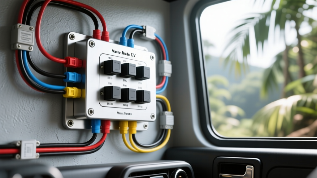
Why Choose Marine-Grade Switch Panels for Automotive Builds?
When building an expedition truck, off-road Jeep, or custom overland rig, standard automotive toggle switches quickly fail under harsh conditions. Dust, water ingress, and extreme UV exposure degrade cheap plastic housings and corrode exposed brass terminals. This is why professional 12-volt system integrators increasingly specify marine-grade rocker switch panels. Designed to meet stringent ABYC (American Boat and Yacht Council) standards, these panels offer IP67 or IP68 waterproof sealing, UV-stabilized polycarbonate facias, and tin-plated copper contacts that resist galvanic corrosion.
However, adapting a marine 12v switch panel wiring diagram to an automotive electrical architecture requires a clear understanding of relay integration, busbar grounding, and appropriate AWG wire sizing. Unlike factory automotive harnesses that rely on multiplexed CAN-bus signals, marine panels utilize heavy-duty, high-amperage mechanical switching or direct relay-triggering. This guide compares the top marine switch systems on the market and provides the technical blueprint for executing a flawless, weatherproof installation in your vehicle.
Top Marine 12V Switch Panel Systems Compared
Selecting the right panel depends on your amperage requirements, dashboard cutout dimensions, and illumination preferences. Below is a comparison of the industry-leading systems used in custom automotive and marine applications.
| Brand / Series | IP Rating | Max Continuous Amps | Terminal Type | Illumination |
|---|---|---|---|---|
| Blue Sea Systems Contura V | IP67 (Panel Face) | 20A @ 12V DC | 0.250' (6.35mm) Spade | LED (Independent/Dependent) |
| Carling Technologies V-Series | IP68 (Sealed Boot) | 20A @ 12V DC | 0.250' (6.35mm) Spade | Incandescent / LED |
| BEP Marine Contura II | IP67 | 20A @ 12V DC | 0.250' (6.35mm) Spade | LED (Single Color) |
| Nilight / Bussmann ATC Kits | IP65 (Splash Proof) | 30A (Relay Fed) | Solder / Harness Plug | LED (Pre-wired) |
Note: While Nilight and Bussmann kits are popular for budget off-road builds due to their included relay harnesses, Blue Sea and Carling panels are the professional standard for custom dash integrations due to their modular terminal architecture and superior ingress protection.
Decoding the Marine 12V Switch Panel Wiring Diagram
When consulting a marine 12v switch panel wiring diagram, it is critical to understand the pinout of the standard 7-pin SPST/SPDT Contura V-Series rocker switch. Unlike simple 2-pin automotive toggles, these switches feature integrated LED illumination circuits that must be wired correctly to prevent short circuits and blown fuses.
Standard 7-Pin Contura Rocker Switch Pinout
- Pin 3 (Line / Source): The main 12V+ power input from the fused busbar. This pin is the 'Common' terminal.
- Pin 2 (Load): The switched 12V+ output. This connects to your accessory (or the trigger coil of a relay). It only receives power when the switch is in the ON position.
- Pin 7 (Dependent Lamp +): 12V+ input for the lower LED lens. Wiring this to an ignition-switched source ensures the switch illuminates only when the vehicle is on.
- Pin 8 (Ground Lamp -): Ground path for the lower LED lens. Must be tied to a clean chassis ground or negative busbar.
- Pin 1 (Independent Lamp +): 12V+ input for the upper indicator LED. Often wired to a separate dash-light dimmer circuit.
- Pins 4 & 5: Typically unused on standard SPST (Single Pole Single Throw) ON-OFF switches, but utilized as secondary load outputs on SPDT (ON-OFF-ON) momentary switches for winch solenoids.
Power Feed and Grounding Architecture
Never daisy-chain the main power feed across the back of the switch panel. The cumulative amperage of multiple switches will melt 14 AWG jumper wires, leading to thermal runaway and potential fire. Instead, use a Blue Sea Systems ST BusBar (rated for 130A continuous). Run a single, heavy-gauge feed wire (typically 8 AWG or 6 AWG tinned copper) from your auxiliary battery or main distribution block to the positive busbar, protected by a master MIDI or ANL fuse. Use 14 AWG or 12 AWG wire to jumper from the busbar to Pin 3 on each individual switch.
Relay Integration for High-Draw Accessories
Most marine rocker switches are rated for 20 amps continuous. However, automotive accessories like 50-inch LED light bars, onboard air compressors, and cooling fans frequently exceed this rating or draw massive inrush currents. To protect the switch contacts from arcing and pitting, you must use the switch to trigger a standard ISO 5-pin automotive relay.
Bosch-Style ISO Mini Relay Wiring (5-Pin)
- Pin 86 (Coil +): Connect to Pin 2 (Load Out) of the marine rocker switch.
- Pin 85 (Coil -): Connect to chassis ground. Pro Tip: If your relay has an internal flyback diode, Pin 86 must be positive and Pin 85 must be negative, or the diode will short the circuit and blow the switch fuse.
- Pin 30 (Common Input): Connect directly to the 12V+ battery or auxiliary fuse block via an appropriately sized inline ATC/ATO fuse.
- Pin 87 (Normally Open Output): Connect to the positive terminal of your high-draw accessory (e.g., light bar).
- Pin 87a (Normally Closed): Left unused and insulated for standard ON/OFF accessory circuits.
By utilizing this relay architecture, the heavy current flows directly from the battery to the load, while the marine switch only carries the fractional amperage required to energize the relay coil (typically 150mA to 300mA). For comprehensive relay and circuit protection guidelines, refer to the Blue Sea Systems Circuit Protection Guide.
Wire Gauge & Overcurrent Protection Chart
Automotive environments subject wiring to high ambient under-hood temperatures and vibration. Adhering to SAE J1128 standards for low-tension primary cable is mandatory. The chart below dictates the minimum AWG size and fuse rating based on circuit length and maximum continuous draw.
| Max Load (Amps) | Wire Length (Under 10 ft) | Wire Length (10 - 20 ft) | Recommended Fuse (ATC/MAXI) |
|---|---|---|---|
| 5A - 10A | 16 AWG | 14 AWG | 10A |
| 11A - 15A | 14 AWG | 12 AWG | 15A |
| 16A - 20A | 12 AWG | 10 AWG | 20A |
| 21A - 35A | 10 AWG | 8 AWG | 30A / 40A |
| 36A - 50A | 8 AWG | 6 AWG | 50A (MIDI) |
Note: For marine environments or vehicles frequently exposed to water and road salt, upgrade from standard SAE copper wire to UL 1426 Tinned Marine Wire. The tin plating prevents copper oxide formation (black wire syndrome), which increases resistance and causes severe voltage drop over time.
Environmental Sealing and Termination Best Practices
The weakest point in any custom 12V installation is the terminal connection. Standard vinyl-insulated crimp connectors will wick moisture via capillary action, leading to green corrosion inside the wire strands.
- Strip and Crimp: Use a precision wire stripper to avoid nicking the copper strands. Crimp using a ratcheting crimper calibrated for the specific terminal gauge to ensure a gas-tight mechanical bond.
- Adhesive-Lined Heat Shrink: Always use dual-wall, adhesive-lined heat shrink terminals (or slide-on 3M FP-301 tubing). When heated, the inner thermoplastic adhesive melts and flows into the wire strands, creating a 100% waterproof environmental seal.
- Terminal Sizing: Marine switch panels universally use 0.250-inch (6.35mm) male spade terminals. Ensure you are using the correct female quick-disconnect terminals with internal locking barbs to prevent vibration-induced disconnects.
Common Failure Modes and Troubleshooting
Even with a perfect marine 12v switch panel wiring diagram on paper, real-world execution can yield faults. Here is how to diagnose the most common issues:
- Symptom: Switch LED flickers or glows dimly when OFF.
Cause: Induced voltage from running the LED illumination wire (Pin 7) parallel to high-current AC alternator lines or ignition coil wires.
Fix: Reroute low-voltage illumination wires away from ECU harnesses and ignition coils. Add a 10k-ohm pull-down resistor between Pin 2 and Ground to bleed off phantom voltage. - Symptom: Switch feels hot to the touch after 10 minutes of use.
Cause: The accessory is drawing more amperage than the 20A switch rating, or the spade terminals are loose, creating high resistance.
Fix: Measure amperage with an inline clamp meter. If over 15A continuous, rewire the circuit to trigger a relay. Squeeze loose female spade terminals with needle-nose pliers for a tighter grip. - Symptom: Main panel fuse blows immediately upon switching on multiple accessories.
Cause: Inrush current. Devices like air compressors and large LED drivers draw 2x to 3x their rated continuous amperage for the first few milliseconds.
Fix: Upgrade the master busbar fuse to a slow-blow (Time-Delay) MIDI fuse, which tolerates brief inrush spikes without opening the circuit.
Final Integration Thoughts
Integrating a marine-grade switch panel into an automotive platform bridges the gap between rugged environmental survivability and clean, logical circuit management. By strictly adhering to proper relay isolation, utilizing tinned copper wiring, and executing gas-tight, adhesive-sealed crimps, your custom 12V accessory panel will outlast the vehicle itself. For further reading on marine terminal standards and corrosion prevention, review the ABYC Technical Standards Overview and the Carling Technologies Contura Specification Sheets.