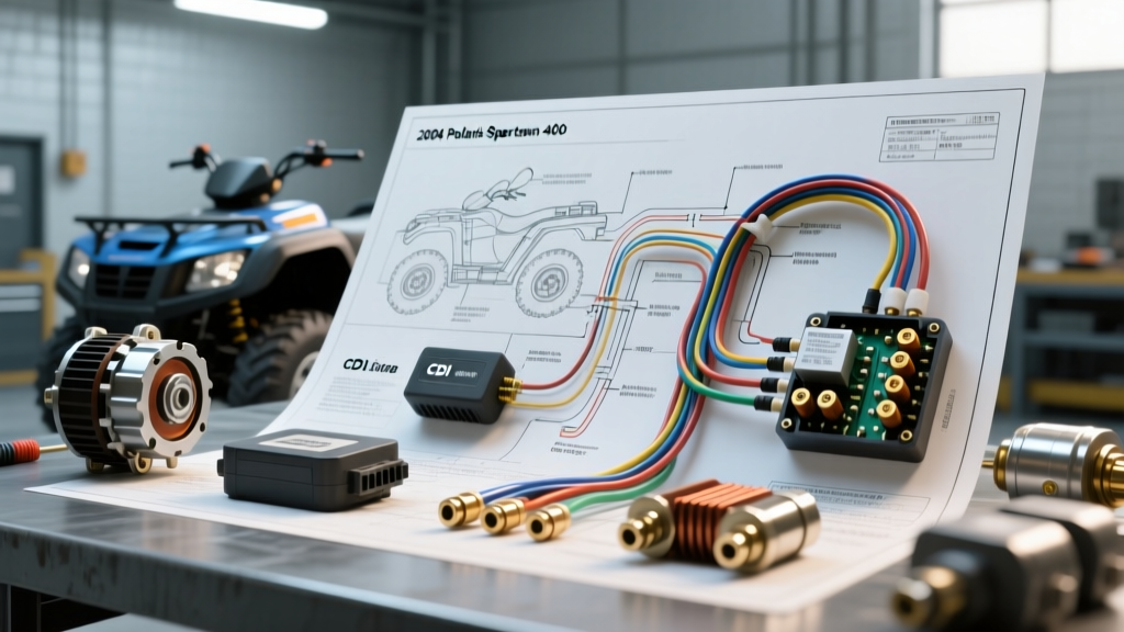
Navigating the 2004 Polaris Sportsman 400 Wiring Diagram
The 2004 Polaris Sportsman 400 utilizes a magneto-driven Capacitor Discharge Ignition (CDI) system paired with a single-phase stator for auxiliary lighting and battery charging. Unlike modern battery-fired EFI systems, the 2004 400cc engine can generate a spark and run even with a completely disconnected or dead battery, provided the stator ignition coil, pickup sensor, and CDI module are functioning correctly. However, this independence makes electrical diagnostics counterintuitive for technicians accustomed to automotive 12V DC logic. When referencing the 2004 Polaris Sportsman 400 wiring diagram, it is critical to separate the high-voltage ignition circuit from the low-voltage DC charging and starting circuits. This guide provides a structured, step-by-step troubleshooting flow to isolate faults in the stator, Voltage Regulator/Rectifier (VRR), CDI, and starter solenoid, utilizing precise Digital Multimeter (DMM) testing protocols and factory wiring color codes.
Master Wire Color Code & AWG Specification Chart
Before initiating any diagnostic flow, verify your harness against the factory color codes. Polaris uses specific gauge sizes based on SAE J1128 standards for low-tension primary cables to handle the thermal loads of off-road environments. Always reference the SAE J1128 Low Tension Cable specifications when replacing damaged harness segments.
| Wire Color | Circuit Function | AWG Size | Connector / Terminal Type |
|---|---|---|---|
| Red | Ignition Power (Stator to CDI) | 18 AWG | AMP Superseal 1.5 |
| White | Pickup Coil / Pulsar Signal | 20 AWG | AMP Superseal 1.5 |
| Black/Yellow | Ignition Kill (Ground to Stop) | 18 AWG | Molex MX150 |
| Yellow / Yellow | AC Lighting / Charging Output | 14 AWG | Weatherpack 2-Pin |
| Black | Main Chassis Ground | 10 AWG | Ring Terminal (5/16') |
| Red (Heavy) | Battery Positive to Solenoid | 6 AWG | High-Amp Ring Terminal |
Troubleshooting Flow 1: No Spark / Ignition Failure
Because the 2004 Sportsman 400 uses a magneto-fired CDI, a no-spark condition is almost never caused by a dead battery. Follow this decision tree to isolate the ignition fault.
Step 1: Kill Switch & Tether Circuit Verification
The Polaris ignition system is 'normally grounded' to kill the spark. The CDI fires only when the Black/Yellow wire is isolated from ground.
- Set DMM to Continuity/Ohms (200Ω).
- Disconnect the main CDI harness connector.
- Probe the Black/Yellow wire terminal on the harness side and a known good chassis ground.
- Decision Point: With the ignition key ON and the run/stop switch in 'RUN', you should read OL (Open Loop). If you read less than 5.0 ohms, the kill switch, tether lanyard, or key cylinder is internally shorted to ground, dumping the CDI charge before it reaches the coil.
Step 2: Pickup Coil (Pulsar) Resistance & AC Output
The pickup coil tells the CDI exactly when to fire the ignition coil based on flywheel magnet passage.
- Static Resistance Test: Set DMM to 2kΩ. Probe the White wire and the Black (ground) wire at the stator connector. Specification is 110Ω to 180Ω at 70°F. A reading of OL indicates an internal winding break.
- Dynamic AC Voltage Test: Set DMM to 20V AC. Connect probes to the White wire and ground. Crank the engine using the recoil starter (recoil provides a more consistent cranking RPM than a weak battery/starter). You must see a minimum of 2.5V AC while cranking. If resistance is correct but AC output is below 2.0V, the flywheel magnet has demagnetized or the air gap exceeds the 0.020' maximum tolerance.
Step 3: CDI Output & Ignition Coil Verification
If the stator and pickup are confirmed functional, the fault lies in the CDI or the ignition coil. According to RM Stator technical diagnostic protocols, testing CDI output requires a peak voltage adapter, as standard DMMs cannot read the microsecond discharge pulse. Instead, test the ignition coil primary and secondary windings. Primary resistance (Black to Orange wire) should be 0.4Ω to 0.8Ω. Secondary resistance (Spark plug cap to ground) must be 3,500Ω to 5,000Ω. Replace the coil if readings fall outside these parameters.
Troubleshooting Flow 2: Battery Not Charging (VRR Diagnostics)
The 2004 Sportsman 400 relies on a single-phase stator winding and a shunt-style Voltage Regulator/Rectifier (VRR) to maintain the 12V battery. A dead battery or flickering headlights requires a systematic AC-to-DC trace.
Step 1: Stator Lighting Coil Output Test
- Disconnect the 2-pin Weatherpack connector linking the stator to the VRR (Yellow wires).
- Set DMM to 200V AC.
- Start the engine and bring it to 3,000 RPM.
- Probe the two Yellow wires on the stator side of the connector.
- Specification: You must read between 28V AC and 45V AC. If voltage is low or fluctuating wildly, the stator lighting coil is burnt out or the flywheel woodruff key has sheared, altering ignition and charging timing.
Step 2: VRR Rectification and Regulation Test
- Reconnect the Yellow wires to the VRR.
- Set DMM to 20V DC.
- Probe the VRR DC output wire (typically Red) and the VRR ground wire (Black) at the battery terminals.
- Specification: At 2,500 RPM, DC voltage must stabilize between 13.8V DC and 14.4V DC.
- Failure Mode: If AC input is >28V but DC output remains at 12.5V or drops as RPMs rise, the internal silicon diodes or the SCR shunt circuit inside the VRR have failed. The VRR must be replaced. Ensure the VRR mounting bolts are torqued to 8-10 ft-lbs to guarantee a proper chassis ground, which is essential for the internal rectifier bridge to function.
Troubleshooting Flow 3: Starter Solenoid & Cranking Faults
The starter circuit on the 2004 400cc model is protected by a 30A main fuse and relies on a heavy-duty relay (solenoid). Use this decision tree when the engine fails to crank.
- Symptom: Solenoid clicks, but engine does not turn over.
- Cause: High resistance across the solenoid internal contacts or a weak battery.
- Fix: Set DMM to DC Volts. Probe the battery-side stud and the starter-side stud on the solenoid while pressing the start button. If you read more than a 0.5V drop across the solenoid while cranking, the internal copper contacts are pitted. Replace the solenoid.
- Symptom: No click, solenoid is completely silent.
- Cause: Open circuit in the trigger wire or safety interlock switch failure.
- Fix: Probe the trigger wire (Yellow/Red) at the solenoid spade terminal. Press the start button. You must read 12V DC. If 0V, trace the circuit backward through the brake light switch (if equipped on the left lever) and the handlebar start button. Corrosion inside the handlebar switch housing is a notorious failure point on 2000-2005 Polaris models due to water ingress. Disassemble, clean with contact cleaner, and apply dielectric grease.
Critical Grounding Points & Connector Maintenance
Over 60% of electrical gremlins on the 2004 Sportsman 400 stem from poor ground connections rather than failed components. The main chassis ground (10 AWG Black wire) terminates on the engine block near the starter motor. This area is constantly exposed to water, mud, and corrosive debris. When performing harness repairs, never use solder-only connections in the engine bay; the vibration of the 400cc single-cylinder engine will cause solder joints to fatigue and fracture. Always use adhesive-lined heat shrink crimp connectors. For all multi-pin connectors, apply a marine-grade dielectric grease to prevent capillary action from drawing moisture into the AMP Superseal terminals. For comprehensive factory torque specs and exploded harness views, always consult the official Polaris OEM Service Manuals portal before tearing down the front pod or magneto cover.