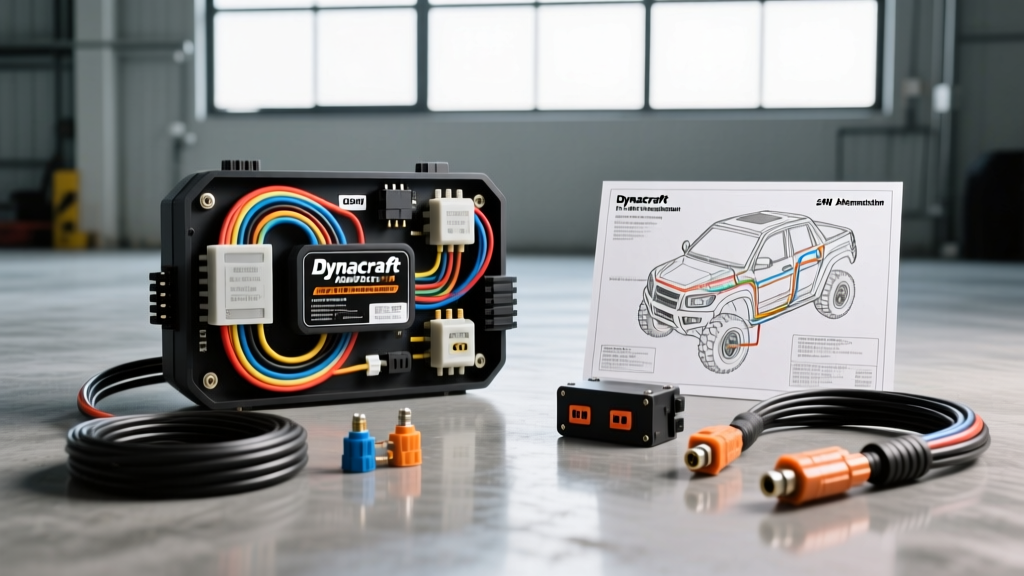
Introduction to 24V Ride-On Electrical Systems
The Dynacraft Realtree 24V UTV is one of the most popular battery-powered off-road vehicles for youth riders, offering authentic styling and dual-motor 24-volt propulsion. However, like all high-current DC ride-on toys, the electrical system is subjected to immense stress. Stall currents from the 24V DC gear motors can easily exceed 25 amps per motor, generating significant heat and voltage drop across the factory wiring harness. For parents, hobbyists, and small-engine repair technicians, understanding the exact Dynacraft Realtree 24V UTV wiring diagram is critical not just for basic troubleshooting, but for selecting the right replacement components when the OEM harness inevitably fails.
This comprehensive product comparison and selection guide breaks down the factory wiring architecture, compares OEM replacement harnesses against heavy-duty aftermarket 24V conversion kits, and provides the technical specifications needed to upgrade the vehicle safely. Whether you are replacing a melted foot pedal switch or upgrading to a golf-cart-style contactor system, selecting the correct wiring components ensures longevity and prevents electrical fires.
Decoding the Dynacraft Realtree 24V UTV Wiring Diagram
Before selecting replacement parts, you must understand the baseline electrical topology of the Realtree 24V system. The vehicle relies on two 12V 12Ah Sealed Lead Acid (SLA) batteries wired in series to produce 24V DC. According to the Battery Council International SLA Guide, a fully charged 24V SLA system will peak at roughly 25.6V under no load, but will sag to 21V-22V under heavy motor stall conditions.
Core Wiring Architecture and Wire Colors
- Main Power Trunk: 12 AWG Red (24V+) and Black (Ground) wires route from the battery compartment to the main relay/control module.
- Foot Pedal Switch: Typically a simple microswitch. The OEM harness routes full motor current through this switch using 14 AWG Red and White wires. This is a primary failure point.
- Forward/Reverse Shifter: A 6-pin DPDT (Double Pole Double Throw) switch. Uses 16 AWG Yellow, Blue, Green, and Orange wires to swap polarity to the motors.
- Motor Leads: 12 AWG or 14 AWG wires connecting the shifter/relays directly to the 24V 550-size DC gear motors.
The 6-Pin DPDT Shifter Pinout (Polarity Reversal)
The most complex part of the Dynacraft wiring diagram is the shifter switch, which acts as a manual H-bridge to reverse motor direction. If you are bypassing a melted OEM switch or selecting an aftermarket heavy-duty toggle, you must wire the DPDT switch in an 'X' cross pattern to achieve polarity reversal without shorting the 24V system.
- Pin 2 (Center Left): 24V+ Input from Foot Pedal / Main Relay.
- Pin 5 (Center Right): Ground (-) Input from Battery Negative.
- Pins 1 & 6 (Top/Bottom Left): Jumpered together, then routed to Motor Lead A.
- Pins 3 & 4 (Top/Bottom Right): Jumpered together, then routed to Motor Lead B.
- Forward Actuation: Internal contacts bridge Pin 2 to Pin 1 (Motor A gets +), and Pin 5 to Pin 4 (Motor B gets -).
- Reverse Actuation: Internal contacts bridge Pin 2 to Pin 3 (Motor B gets +), and Pin 5 to Pin 6 (Motor A gets -).
Product Comparison: OEM vs. Aftermarket 24V Wiring Harnesses
When the factory wiring fails, technicians and DIYers face a critical selection decision: replace with an exact OEM replica harness, or upgrade to an aftermarket 24V relay/contactors kit. Below is a technical comparison of the three primary wiring solutions available for the Dynacraft Realtree 24V UTV.
| Feature | OEM Dynacraft Harness | Generic 24V Relay Bypass Kit | HD Golf-Cart Contactor Kit |
|---|---|---|---|
| Max Continuous Current | 15 Amps (per circuit) | 30 Amps (per relay) | 80+ Amps (per contactor) |
| Foot Pedal Switch Type | Direct-load Microswitch | Low-current Logic Trigger | Low-current Logic Trigger |
| Main Wire Gauge | 14 AWG Copper | 12 AWG Copper | 10 AWG or 8 AWG Copper |
| Switching Mechanism | Direct Mechanical Contact | Standard 5-Pin Automotive Relays | 24V DC Solenoid Contactors |
| Expected Lifespan | 1-2 Years (Heavy Use) | 3-4 Years | 5+ Years (Industrial Grade) |
| Estimated Cost | $25 - $40 | $45 - $65 | $85 - $130 |
Component Selection Guide: Relays vs. DC Contactors
The most significant upgrade you can make to the Realtree 24V wiring diagram is removing the direct-load foot pedal switch and installing a remote switching mechanism. However, selecting the correct type of switch is vital for 24-volt DC systems.
Why Standard 12V Automotive Relays Fail at 24V
Many budget aftermarket kits utilize standard 12V automotive SPST relays (like the common Bosch-style 5-pin cube) wired in series or rated for '12V/24V universal use'. According to the Littelfuse Automotive Relay Application Guide, breaking a 24V DC inductive load (like a spinning gear motor) generates a significantly larger and hotter electrical arc than a 12V load. Standard automotive relays lack the internal contact gap and arc-extinguishing magnets required for 24V DC motor loads. Over time, the contacts weld together, causing the UTV to run away uncontrollably even when the foot pedal is released.
Selecting a 24V DC Contactor
For a permanent, safe upgrade, select a dedicated 24V DC contactor (often used in electric golf carts or winches). These feature larger contact gaps, heavier copper bussing, and are designed to handle the 50A+ inrush current of dual 24V motors starting from a dead stop. When selecting a contactor kit, ensure the coil voltage is rated specifically for 24V DC, and that the main power lugs accept at least 10 AWG ring terminals.
Wire Gauge, Insulation, and Terminal Selection
When fabricating custom harnesses or repairing the OEM diagram, wire selection must adhere to strict automotive standards. The SAE J1128 Low Tension Primary Cable Standard dictates the insulation thickness and temperature ratings for automotive wiring. For the Realtree 24V UTV, standard PVC household wire (THHN) is unacceptable due to its stiffness and poor vibration resistance.
- Wire Type: Always select SAE J1128 compliant GXL or TXL cross-linked polyethylene (XLPE) insulated wire. TXL is preferred for ride-ons due to its thinner insulation wall, allowing for easier routing through tight chassis grommets while maintaining a 125°C temperature rating.
- Main Battery to Contactor: 10 AWG or 8 AWG Stranded Copper.
- Contactor to Motors: 12 AWG Stranded Copper.
- Logic / Switch Wiring: 16 AWG or 18 AWG (Pedal trigger, shifter logic, horn, and radio).
- Terminals: Avoid standard vinyl-insulated crimp caps. Use adhesive-lined heat-shrink ring terminals and closed-barrel crimpers to prevent moisture ingress and wire pull-out caused by chassis vibration.
Troubleshooting Common Wiring Failures
Use this diagnostic decision tree to identify faults within the Dynacraft Realtree 24V wiring harness before purchasing replacement components.
- Symptom: UTV clicks when pedal is pressed, but motors do not spin.
- Cause: Voltage drop across corroded battery series jumper, or failing SLA battery unable to sustain load.
- Fix: Check voltage at the battery terminals *while* the pedal is pressed. If it drops below 18V, replace the SLA batteries and upgrade the series jumper wire to 12 AWG.
- Symptom: UTV only drives in Reverse, but not Forward.
- Cause: Melted or oxidized contacts inside the 6-pin DPDT shifter switch on pins 1 or 2.
- Fix: Bypass the shifter switch temporarily using jumper wires to confirm motor health. If motors run, replace the shifter with a heavy-duty marine-grade DPDT toggle switch rated for 20A+.
- Symptom: Foot pedal feels 'sticky' or smells like melting plastic.
- Cause: The OEM microswitch is arcing internally and melting the plastic housing due to running 25A+ through a 5A rated switch.
- Fix: Discard the direct-load pedal. Install a 24V DC contactor and rewire the pedal to act only as a low-current (1A) logic trigger for the contactor coil.
Final Selection Recommendations
If your Dynacraft Realtree 24V UTV is used lightly on flat grass, an OEM replacement harness is a cost-effective and straightforward repair. However, if the vehicle is driven aggressively, modified with larger tires, or operated on inclines, the OEM direct-load switches will fail repeatedly. Investing in an aftermarket Heavy-Duty Contactor Kit and rewiring the system to SAE J1128 standards transforms the toy's electrical system into a reliable, industrial-grade setup that mirrors full-size UTV electrical architectures.