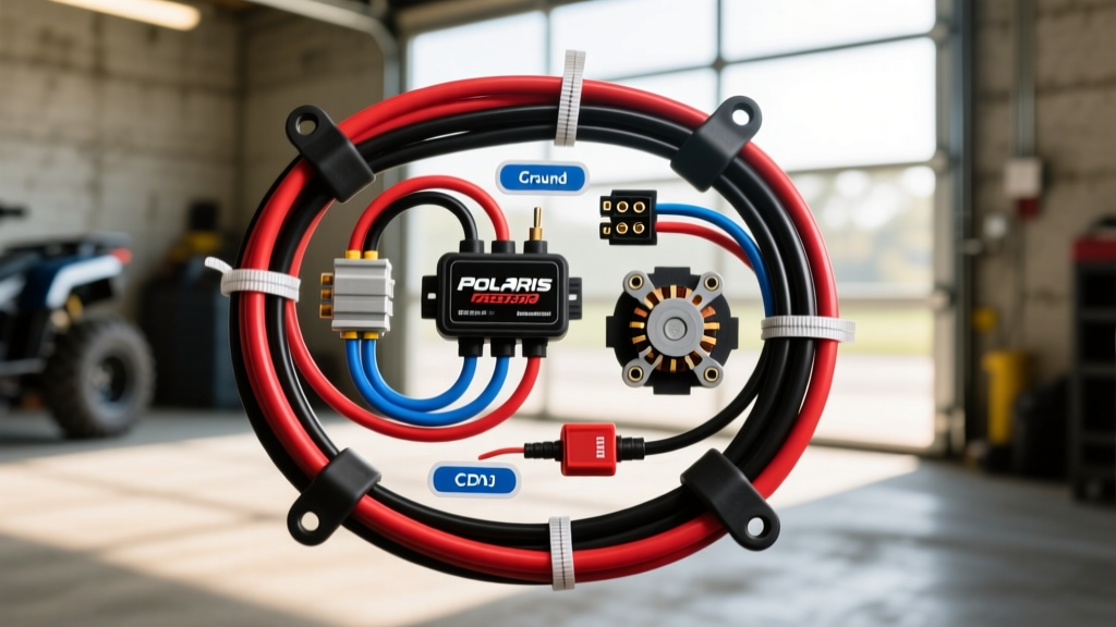
Understanding the Polaris Predator 90 Electrical Architecture
When diagnosing a no-spark or total electrical failure on a youth ATV, referencing an accurate Polaris Predator 90 wiring diagram is critical. Unlike modern fuel-injected UTVs, the classic Polaris Predator 90 (2003-2006 2-stroke models) relies on a magneto-driven AC electrical system. It does not use a traditional 12V battery charging system for ignition; instead, the stator generates raw AC voltage to feed the Capacitor Discharge Ignition (CDI) module directly. The lighting circuit operates independently on a separate stator winding. Understanding this isolation is the first step in our diagnostic flow.
Because the Predator 90 is subjected to extreme vibrations, mud, and water ingress, the most common failure modes are not dead components, but rather corroded Sumitomo/Molex connectors, rubbed harness insulation near the steering stem, and compromised ground paths. This guide provides a step-by-step troubleshooting flow to isolate faults in the CDI, stator, and ignition coil circuits using exact factory pinouts and resistance specifications.
Predator 90 CDI & Stator Pinout Reference Table
Before testing, verify your harness colors against the factory CDI connector. Polaris typically uses a 5-pin or 6-pin weather-sealed connector for the CDI module. Below is the standard pinout for the 2-stroke Predator 90 CDI system.
| CDI Pin | Wire Color | Function | Source / Destination |
|---|---|---|---|
| 1 | Black | System Ground | Engine Case / Frame Ground |
| 2 | White/Red | Trigger / Pulse Signal | Stator Trigger Coil |
| 3 | Black/Red | Source AC Power | Stator Source Coil |
| 4 | Black/Yellow | Coil Primary Output | Ignition Coil Primary |
| 5 | Black/White | Kill Switch Circuit | Handlebar Switch / Tether |
| N/A | Yellow | Lighting AC Output | Stator Lighting Coil to Lights |
Step-by-Step Troubleshooting Flow: No Spark Condition
Follow this sequential flow to isolate the cause of a no-spark condition. Do not skip steps, as a faulty kill switch will mimic a dead CDI module.
Step 1: Verify the Kill Switch and Tether Circuit
Symptom: Engine cranks/pulls over but no spark at the plug.
The Test: The kill circuit on the Predator 90 operates by grounding the CDI. Pin 5 (Black/White wire) must have an open circuit to ground for the engine to run, and continuity to ground to kill the engine.
- Disconnect the main harness connector near the CDI.
- Set your digital multimeter (DMM) to Ohms (Continuity).
- Probe the harness-side Pin 5 (Black/White) and a known good engine ground.
- Toggle the handlebar kill switch to 'RUN' and pull the tether lanyard out.
Pass/Fail: If you read continuity (less than 1.0 ohm) with the switch in the 'RUN' position, you have a short to ground. Inspect the handlebar switch pod for moisture ingress and trace the Black/White wire down the steering stem where it commonly rubs against the chassis.
Step 2: Stator Source Coil and Trigger Coil Test
Symptom: Kill switch circuit is verified open, but still no spark.
The Test: The CDI requires two inputs from the stator: high-voltage AC from the Source Coil (Pin 3, Black/Red) and a timing pulse from the Trigger Coil (Pin 2, White/Red).
- Resistance Check (Static): Disconnect the stator plug. Measure resistance between the Black/Red wire and ground. Factory spec is typically 45-65 ohms. Measure the White/Red wire to ground; spec is 90-150 ohms. An infinite reading (OL) indicates an internal stator break.
- Peak Voltage Check (Dynamic): Standard multimeters cannot read the fast, high-voltage pulses of a magneto. You must use a DVA (Direct Voltage Adapter) or a DMM with a 'Peak Hold' function. Connect the DVA to the Black/Red wire and ground while cranking/pulling the starter. You should see a minimum of 100V to 150V Peak. If voltage is below 80V, the stator source coil or the flywheel magnets are failing.
Expert Insight: According to diagnostic guidelines from RMSTATOR, a common failure on the Predator 90 is the flywood woodruff key shearing, which slightly rotates the flywheel. This alters the air gap and timing, resulting in weak or no spark despite the stator testing within spec. Always verify flywheel alignment if stator ohms are good but the engine backfires.
Step 3: CDI Module Input/Output Verification
Symptom: Stator outputs are within spec, kill circuit is open, but no spark.
The Test: The CDI acts as a capacitor and switch. It stores the AC voltage from the Source Coil and dumps it into the Ignition Coil when it receives the pulse from the Trigger Coil.
- Reconnect the stator and CDI.
- Backprobe Pin 4 (Black/Yellow) at the CDI connector using a DVA adapter.
- Crank the engine. You should see a massive spike in voltage (often exceeding 200V Peak) as the CDI fires the coil.
Pass/Fail: If you have correct inputs on Pins 2 and 3, an open circuit on Pin 5, but zero output on Pin 4, the CDI module is internally faulted and must be replaced. CDI modules are solid-state and cannot be repaired.
Step 4: Ignition Coil and Spark Plug Cap Resistance
Symptom: CDI is firing Pin 4, but no spark at the plug.
The Test: The ignition coil steps up the CDI's voltage to 20,000+ volts to jump the spark plug gap.
- Disconnect the Black/Yellow wire from the coil primary terminal.
- Measure Primary Resistance: Place one probe on the primary terminal and the other on the coil mounting bracket (ground). Spec: 0.1 to 0.5 ohms.
- Measure Secondary Resistance: Remove the spark plug cap. Place one probe inside the coil tower (where the cap screws in) and the other on the core wire of the spark plug cap. Spec: 5,000 to 15,000 ohms (5k - 15k).
Expert Insight: The Predator 90 spark plug cap contains a 5k ohm ceramic resistor. If the cap gets waterlogged or the internal spring corrodes, resistance will spike, choking the spark. Always replace the cap with an OEM NGK resistor cap when replacing the coil.
Troubleshooting the Lighting Circuit (No Headlights)
The lighting circuit on the Predator 90 is completely isolated from the CDI. It is powered by the Yellow wire exiting the stator. This is a raw AC voltage system that feeds directly to the headlight bulb via the handlebar light switch.
- Symptom: Headlights flicker wildly with RPM or burn out bulbs frequently.
- Cause: The Predator 90 relies on the load of the headlight bulb to regulate the lighting coil voltage. If a bulb blows, or if a previous owner installed an LED light bar (which draws significantly less amperage than a halogen bulb), the AC voltage will spike uncontrolled, often exceeding 40V AC at high RPM.
- Fix: Never wire aftermarket LED bars directly to the Yellow stator wire without an inline AC-to-DC rectifier and a 12V voltage regulator. For reference on proper automotive wire gauge selection for aftermarket lighting, consult the SAE J1128 standard for low-tension primary cable specifications to ensure your added harness can handle the AC amperage without voltage drop.
Common Wiring Failure Modes & Harness Repairs
When the Polaris Predator 90 wiring diagram points to a broken circuit, how you repair the harness dictates how long the fix will last. Standard electrical tape and twist-crimp connectors will fail within weeks in an off-road environment.
1. Steering Stem Harness Chafing
The main harness routes from the CDI (under the seat/fender) up to the handlebar switch pod. Over time, the steering limiter and chassis brackets wear through the loom, causing the Black/White (kill) or Yellow (lighting) wires to short to the frame.
Repair Protocol: Cut out the damaged section. Splice using 18 AWG cross-linked polyethylene (XLPE) wire. Solder the connections using rosin-core solder, then seal with adhesive-lined marine heat shrink. The adhesive lining melts and seals out moisture, preventing green-crust corrosion.
2. Corroded CDI Ground (Pin 1)
The CDI grounds through the Black wire, which often terminates at the engine mounting bolt or a frame tab. Vibration causes the ring terminal to loosen, introducing resistance. A high-resistance ground will cause the CDI to misfire at high RPM.
Repair Protocol: Remove the ground bolt. Clean the mating surface on the engine case with a wire wheel down to bare aluminum. Apply a thin layer of dielectric grease to the terminal to prevent galvanic corrosion, and torque the bolt to 18 ft-lbs.
3. Stator Plug Moisture Ingress
The stator plug is located low on the engine case, constantly exposed to water and mud. If the rubber weather seals dry out, water bridges the Trigger and Source pins, causing the spark to jump internally rather than reaching the CDI.
Repair Protocol: Disconnect the plug, clean the pins with electrical contact cleaner, and pack the back of the connector cavity with a marine-grade dielectric grease (such as Super Lube or NYE 812). This displaces moisture and prevents future corrosion. For OEM replacement parts and factory exploded diagrams, resources like Partzilla's Polaris ATV archives are invaluable for verifying exact part numbers for updated harness assemblies.
Final Diagnostic Summary
Troubleshooting the Polaris Predator 90 electrical system requires a methodical approach. By isolating the kill circuit first, verifying stator peak voltages with a DVA, and testing the CDI output, you eliminate guesswork. Always respect the isolation between the AC lighting circuit and the DC-pulse ignition circuit, and prioritize moisture-sealed repairs to ensure the youth ATV remains reliable on the trails.