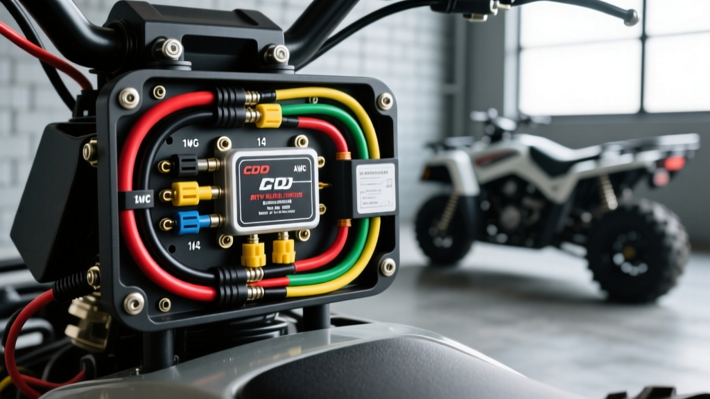
Understanding the ATV Kill Switch Wiring Diagram
When upgrading or replacing the engine stop mechanism on your off-road vehicle, referencing an accurate atv kill switch wiring diagram is critical for both safety and electrical system integrity. Unlike automotive ignition switches that manage high-current starter and accessory circuits, the typical ATV kill switch operates as a low-current signal interrupt. Its primary function is to either ground the ignition coil primary circuit or send a logic-level signal to the Engine Control Module (ECM) to immediately cease spark generation.
Before cutting or splicing a single wire, you must determine whether your specific quad utilizes a Capacitor Discharge Ignition (CDI) system or an Electronic Fuel Injection (EFI) system. Carbureted models (like the Honda TRX300EX or older Polaris Sportsman 500) generally use a Normally Closed (NC) switch that routes the Black/White ignition wire to the chassis ground to kill the spark. Conversely, modern EFI models (like the Can-Am Outlander or Yamaha Raptor 700) often use a Normally Open (NO) switch to interrupt a 12V ignition trigger or communicate a shutdown command via the CAN-bus network.
Tools and Materials Required
To ensure an IP67-waterproof and vibration-resistant installation, avoid cheap hardware store toggle switches and electrical tape. Use automotive-grade materials that meet SAE J1128 standards for low-tension primary cables.
- Wire: 18 AWG TXL (Cross-linked polyethylene) primary wire. TXL is rated for 125°C and features thin insulation, making it ideal for routing through tight handlebar controls.
- Switch: OEM-style NC (Normally Closed) or NO (Normally Open) handlebar switch, or a marine-grade magnetic tether lanyard switch.
- Connectors: Deutsch DT series (DT04-2P receptacle and DT06-2S plug) or OEM-specific WeatherPack terminals.
- Insulation: Adhesive-lined marine heat shrink (3M or equivalent) with a 3:1 shrink ratio to prevent capillary water wicking.
- Tools: Wire strippers, open-barrel terminal crimpers, heat gun, and a digital multimeter (DMM).
Step-by-Step Installation Guide
Step 1: Identify the Ignition Kill Wire
Consult your factory service manual to locate the ignition kill wire at the CDI or ECM harness. For most Honda and Suzuki carbureted ATVs, this is the Black/White wire. For Polaris models, it is often Black/Yellow or Black/White. Use your DMM set to continuity mode. Probe the suspected wire and the chassis ground. With the OEM switch in the "RUN" position, there should be no continuity (OL). Flip the switch to "OFF"; the meter should beep, indicating the circuit is now grounded.
Step 2: Mount the Switch and Route the Harness
Mount the new switch securely to the handlebar using the provided stainless steel clamps. When routing the wire down the steering stem, you must leave a service loop—a deliberate 2-inch slack of wire just below the steering nut. This loop prevents wire fatigue and copper strand breakage when the handlebars are turned lock-to-lock. Secure the harness with UV-resistant zip ties, ensuring the wire does not rub against the steering column or brake lines.
Step 3: Crimp, Solder, and Seal
Strip exactly 5/16" of insulation from the 18 AWG TXL wire. Crimp the Deutsch DT pins using an open-barrel crimping tool. For high-vibration ATV environments, it is best practice to lightly solder the wire-to-terminal connection after crimping, then slide a piece of adhesive-lined heat shrink over the barrel. Apply heat until the adhesive sealant extrudes slightly from the ends, creating a watertight barrier against mud and pressure washing.
Step 4: Integrate the Tether Lanyard (Optional but Recommended)
For racing or aggressive trail riding, wiring a magnetic tether switch in series with the manual thumb switch is a vital safety upgrade. Wire the tether switch so that pulling the lanyard mimics the action of hitting the manual kill switch. If your manual switch is NC (ground-kill), wire the tether as an NC switch in parallel to the ground circuit. If pulling the tether opens the circuit, wire it in series with the 12V ignition feed.
Kill Switch Wiring Pinout & Specification Table
The following table outlines common ignition kill circuit specifications across major ATV manufacturers. Always verify with your specific year and model service manual, as mid-year production changes can alter wire colors.
| Manufacturer / System | Kill Wire Color | Switch Logic | Circuit Action | Wire Gauge |
|---|---|---|---|---|
| Honda (Carb/CDI - TRX300/400EX) | Black/White | Normally Closed (NC) | Grounds CDI to chassis | 18 AWG |
| Polaris (Carb/CDI - Sportsman) | Black/Yellow | Normally Closed (NC) | Grounds Stator/CDI | 18 AWG |
| Yamaha (EFI - Raptor 700) | Red/White (Signal) | Normally Open (NO) | Interrupts 12V ECM trigger | 18 AWG |
| Can-Am (EFI - Outlander) | CAN-Bus / 12V Relay | Normally Open (NO) | Drops ignition relay voltage | 16 AWG (Relay) |
| Suzuki (Carb/CDI - LTZ400) | Black/White | Normally Closed (NC) | Grounds CDI module | 18 AWG |
Note: Data compiled referencing Honda Powersports and Polaris Support technical documentation.
Troubleshooting Common Kill Switch Failures
If your ATV has no spark and you suspect the kill switch circuit, follow this diagnostic decision tree before replacing expensive CDI units or stators.
1. The Engine Will Not Shut Off (Switch Ignored)
- Cause: Broken ground path or corroded switch contacts.
- Fix: Disconnect the switch harness. Use a jumper wire to manually ground the Black/White kill wire directly to the engine block. If the engine dies, the switch or its ground wire is faulty. Check the chassis ground ring terminal for rust or loose torque.
2. The Engine Will Not Start (No Spark)
- Cause: Short to ground in the kill wire harness, or a failed NC switch stuck in the closed position.
- Fix: Unplug the kill switch at the main harness connector near the steering stem. If the ATV immediately gains spark and starts, the switch is internally shorted, or the wire is pinched between the handlebar clamp and the steering column. Inspect the steering column pinch points—a very common failure area on older quads.
3. Intermittent Misfires While Turning
- Cause: Copper strand fatigue inside the wire insulation due to lack of a steering service loop.
- Fix: Perform a continuity test on the kill wire while an assistant turns the handlebars fully left and right. If the DMM beeps intermittently (indicating a momentary short to ground), the wire is internally broken and arcing against the chassis. You must replace the harness segment and add proper slack.
Final Torque and Inspection
Once the wiring is complete and tested, secure all Deutsch connectors until you hear the definitive "click" of the secondary terminal lock. Re-check the handlebar clamp bolts to 15-18 ft-lbs (consult your specific manual), ensuring the switch housing does not crack under overtightening. Finally, spray the switch mechanism with a dielectric grease or silicone-based contact protector to prevent mud intrusion and internal corrosion, ensuring your kill switch operates flawlessly in the harshest off-road environments.