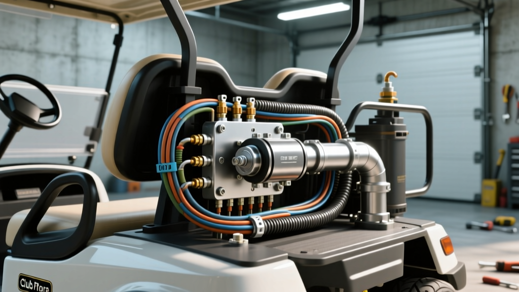
Transforming Your Platform: The Utility Vehicle Wiring Overhaul
When converting a standard golf cart into a true club car electric utility vehicle—whether you are outfitting a Carryall 1500, an XRT, or a modified Precedent with a dump bed and plow—the stock electrical system quickly reaches its limits. Factory wiring is engineered for the intermittent loads of a golf course, not the sustained, high-amperage demands of winching, snow plowing, or hauling heavy payloads up steep grades. Under heavy utility loads, stock 2 AWG cables and standard 400A solenoids suffer from severe voltage sag, which often triggers the motor controller's low-voltage cutoff or causes premature component failure.
This comprehensive upgrade guide details the exact wiring modifications, AWG sizing, and connector standards required to build a bulletproof electrical system for your club car electric utility vehicle. We will cover main battery cable fabrication, heavy-duty solenoid integration, and isolated auxiliary harnesses.
Phase 1: Main Power and Controller Cable Upgrades
The most critical bottleneck in any modified electric utility vehicle is the main battery pack wiring. Stock cables are typically 2 AWG, which is sufficient for 20-30 amp cruising currents but highly restrictive when the motor demands 300+ amps under heavy load or when pulling a winch.
Selecting the Right Cable Standard
For a heavy-duty utility build, discard standard PVC-insulated battery cables. You must use SAE J378 compliant marine-grade tinned copper wire or fine-strand welding cable. According to SAE International standards, fine-strand wire offers superior flexibility and resistance to vibration-induced strand breakage, which is common in utility vehicles operating on rough terrain.
- Main Battery Interconnects: Upgrade from 2 AWG to 1/0 AWG pure copper.
- Controller to Motor Leads: Upgrade to 2/0 AWG to handle peak phase currents from the V-Glide or IQ controller.
- Ground Return Paths: Ensure the main negative busbar is tied directly to the motor casing and the chassis using a minimum 1/0 AWG braided ground strap.
Crimping and Termination Standards
Do not use hammer-style crimpers for 1/0 AWG or larger wire. Utilize a 12-ton hydraulic crimper with a hexagonal die to ensure uniform compression. Following IPC-A-620 wiring harness standards, every termination must be sealed with adhesive-lined, dual-wall heat shrink tubing. The adhesive melts and flows into the wire strands, preventing moisture and battery acid corrosion from creeping under the insulation—a common failure mode in utility vehicles exposed to the elements.
Phase 2: High-Current Solenoid and Winch Integration
Factory Club Car solenoids are generally rated for 400A peak and 150A continuous. When your club car electric utility vehicle is equipped with a front-mount winch or a hydraulic dump bed, the continuous amperage draw can easily exceed 250A, welding the factory solenoid's internal contacts shut.
Upgrading to a Continuous-Duty Solenoid
Replace the stock solenoid with a heavy-duty, continuous-duty contactor such as the Cole Hersee 24059-08 (48V, 600A) or an equivalent Albright SW200 series. As noted in the Littelfuse/Cole Hersee heavy-duty solenoid catalog, these units feature silver-alloy contacts and arc chutes designed to extinguish the massive DC arcs generated by inductive motor and winch loads.
Solenoid Wiring Pinout and Routing:
- Main Terminals (Large Studs): Connect the 1/0 AWG main positive from the battery pack to one side, and the 1/0 AWG feed to the motor controller on the other. Torque 5/16" hardware to exactly 12-15 ft-lbs. Over-torquing can crack the internal ceramic arc chute.
- Coil Terminals (Small Spades/Studs): The activation circuit requires 12 AWG or 10 AWG wire. In most Club Car IQ systems, the small wire from the key switch (often Red/White or Yellow) feeds one coil terminal, while the other routes to the controller's logic ground or pre-charge circuit.
- Pre-Charge Resistor: Never omit the pre-charge resistor (typically 470 ohm, 5W) wired across the main solenoid terminals. This resistor trickle-charges the controller's main capacitors before the solenoid closes, preventing a massive inrush current that will instantly pit your new heavy-duty contacts.
Winch Relay Isolation
Never wire a winch directly through the main drive solenoid. The winch must have its own dedicated, fused relay connected directly to the battery pack's main positive and negative busbars. Use an Anderson SB175 quick-disconnect plug (rated for 175A continuous) between the winch relay and the winch motor, allowing you to completely isolate the winch when not in use to prevent parasitic draw and accidental engagement.
Phase 3: Auxiliary Work Lighting Harness Design
A true club car electric utility vehicle requires high-lumen LED light bars and floodlights for night operations. The most common wiring mistake is tapping accessory lights into the cart's key switch or DC-DC converter without proper relay isolation. This backfeeds voltage into the MCOR (throttle) circuit or overloads the 10A key switch contacts.
Building an Isolated Relay Harness
Use a standalone 48V-to-12V DC-DC converter rated for at least 30A (360W) exclusively for lighting. Wire the output of the DC-DC converter to a centralized fuse block. From there, use standard Bosch-style 12V automotive relays to switch the high-current lighting loads.
- Relay Pin 86 (Coil +): Connect to a dedicated toggle switch on the dash, fed by a low-amp (5A) tap from the DC-DC converter.
- Relay Pin 85 (Coil -): Ground to the chassis or negative busbar.
- Relay Pin 30 (Input): High-current 12V feed from the DC-DC converter's main output, protected by an inline ATC fuse.
- Relay Pin 87 (Output): Feeds the LED light bar using 14 AWG wire and waterproof Deutsch DT series connectors.
Using Deutsch connectors for all exterior lighting ensures an IP68 waterproof seal, preventing the green crust corrosion that plagues standard spade connectors in utility environments.
Technical Reference: 48V System Cable Sizing & Voltage Drop
When building your club car electric utility vehicle, maintaining voltage at the controller is critical. A voltage drop of more than 5% under peak load will cause the controller to derate power or shut down completely. Use the following chart to select your wire gauge based on the maximum expected draw and total cable length (positive and negative combined).
| Wire Gauge (AWG) | Max Continuous Amps | Total Run Length | Voltage Drop at 300A Peak | Recommended Application |
|---|---|---|---|---|
| 2 AWG | 120A | 15 ft | 2.85V (5.9%) | Stock Golf Cart (Not recommended for utility) |
| 1/0 AWG | 190A | 15 ft | 1.50V (3.1%) | Main Battery Interconnects, Solenoid Feeds |
| 2/0 AWG | 225A | 15 ft | 1.18V (2.4%) | Controller to Motor Phase Leads |
| 4/0 AWG | 310A | 15 ft | 0.75V (1.5%) | Extreme Duty Winch / Plow Pump Feeds |
Real-World Troubleshooting and Failure Modes
Even with premium components, improper execution can lead to frustrating electrical gremlins. Here are the most common failure modes encountered after upgrading a club car electric utility vehicle:
Symptom: Cart Clicks but Won't Move Under Heavy Load
Cause: Severe voltage drop across the main solenoid contacts. While the coil is engaging (the "click"), the internal contacts are pitted or the terminal hardware is loose, preventing high amperage from reaching the controller.
Fix: Use a digital multimeter to measure the voltage drop across the large solenoid studs while the cart is under load (chock the wheels and apply throttle). A healthy solenoid will show a drop of less than 0.2V. If it reads over 0.5V, replace the contactor or re-torque the terminals to 15 ft-lbs.
Symptom: LED Work Lights Flicker or Dim When Throttle is Applied
Cause: Ground loop or undersized DC-DC converter. If the lighting ground is tied to a dirty chassis bolt rather than the main negative busbar, the massive current returning from the motor will seek the path of least resistance, pushing back up through the lighting ground wire.
Fix: Implement a "Star Grounding" topology. Run a dedicated 6 AWG ground wire from the DC-DC converter's negative terminal directly to the main battery pack negative post, completely bypassing the chassis.
Symptom: Melted Anderson SB Connectors
Cause: Using the wrong crimp die or failing to seat the pins fully into the plastic housing, causing high resistance at the connection point.
Fix: Ensure you are using the specific Anderson-approved roll-crimp dies for your wire gauge. After crimping, pull firmly on the wire to verify the pin locks into the housing with an audible "click". Apply a thin layer of dielectric grease to the contacts to prevent oxidation.
Final Safety and Maintenance Directives
Upgrading your club car electric utility vehicle transforms it into a highly capable machine, but it also increases the available fault current in the system. Always install a Class-T fuse or a marine-grade ANL fuse (rated 20% higher than your maximum continuous draw) as close to the main battery positive terminal as possible. This ensures that in the event of a dead short or a welded solenoid, the main power is severed before a fire can ignite. Perform an annual thermal scan of all busbars, solenoid terminals, and motor connections using an infrared thermometer; any terminal reading more than 20°F above ambient temperature requires immediate disassembly, wire-brushing, and re-torquing.