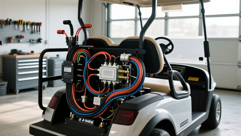
Diagnosing the Root Cause of Electric Golf Cart Problems
When diagnosing electric golf cart problems, owners and fleet technicians often mistakenly blame failing battery packs, worn motor brushes, or defective speed controllers. However, a vast majority of performance issues—ranging from erratic speed sensor lockouts and severe voltage sag to melted directional switches and thermal controller shutdowns—stem from an undersized, degraded factory wiring harness. The E-Z-GO TXT PDS (Precision Drive System) platform, while revolutionary for its era, utilizes factory 4 AWG and 2 AWG battery cables that are highly susceptible to resistance buildup, corrosion, and inductive heat under high-amperage loads.
If your cart exhibits High Pedal Disable (HPD) lockouts, stutters under heavy incline loads, or suffers from melted key switches, you are likely experiencing severe voltage drop. This comprehensive upgrade and modification project will guide you through replacing the entire high-current harness with 1/0 AWG marine-grade cable, installing a heavy-duty 400A continuous solenoid, and implementing a relay-bypass for the ignition circuit to permanently eliminate the most frustrating electrical gremlins in the PDS system.
The High-Amp Upgrade Blueprint
Upgrading the main power delivery system requires adherence to strict automotive electrical standards. According to SAE J1128 standards for low-tension primary cable, minimizing circuit resistance is critical in low-voltage (36V/48V) DC systems where current draw can easily exceed 300 amps during peak torque demands. By moving from 2 AWG to 1/0 AWG wire, we reduce the resistance per foot from 0.156 milliohms to 0.098 milliohms, drastically reducing heat generation and preserving voltage at the motor terminals.
Component Specifications & Sourcing
| Component | Factory Spec | Upgrade Spec | Connection / Hardware |
|---|---|---|---|
| Main Battery Cables | 4 AWG / 2 AWG Copper | 1/0 AWG Tinned Marine Copper | 3/8" Adhesive-Lined Ring Terminals |
| Main Contactor | HD 200A Intermittent | Albright SW200 (400A Cont.) | 3/8" Studs, 15 ft-lbs torque |
| Controller | Curtis 1205-505/525 | Retain Stock (Re-terminate) | 3/8" Ring, 90 in-lbs torque |
| Key Switch Circuit | Direct 12A-15A Load | Trombetta 48V Relay Bypass | 14 AWG Logic Wire, Spade Connectors |
Executing the Main Power Circuit Upgrade
The foundation of this modification involves stripping out the aging factory B+ (Battery Positive), B- (Battery Negative), and Motor Armature cables. Over time, the copper strands inside the factory insulation oxidize, turning black and acting as a resistor. This resistance causes the Curtis Instruments 1205 Controller to read a lower voltage than what is actually present at the battery pack, triggering premature low-voltage rollback (LVR) or thermal throttling.
Step 1: B+ and B- Main Power Routing
- Disconnect the Tow/Run Switch: Place the PDS Tow/Run switch in the "TOW" position to disable the controller and prevent accidental engagement or back-EMF spikes.
- Fabricate 1/0 AWG Cables: Measure and cut 1/0 AWG tinned copper wire. Use a hydraulic crimper to attach 3/8" copper ring terminals. Expert Tip: Always use 3:1 ratio adhesive-lined marine heat shrink. The internal adhesive melts and seals the crimp barrel, preventing moisture and battery acid vapor from wicking into the copper strands.
- Route B+ to the Solenoid: Run the new 1/0 AWG Red cable from the main battery pack positive terminal to the input stud of the new Albright SW200 solenoid. Reference the Albright SW200 DC Contactor datasheet to ensure proper stud orientation and torque the nuts to exactly 15 ft-lbs to prevent micro-arcing.
- Route Solenoid to Controller Pin 1: Run a 1/0 AWG Red cable from the solenoid output stud directly to Pin 1 (B+) on the Curtis 1205 controller. Torque the controller busbar nut to 90 in-lbs (10 Nm). Over-torquing will strip the soft brass threads inside the controller housing.
Step 2: Motor and Shunt Connections
Connect the 1/0 AWG Black cable from the controller Pin 3 (B-) to the negative battery busbar. Next, connect the 1/0 AWG Yellow cable from controller Pin 2 (M-) to the Motor A1 terminal. Ensure all motor terminal nuts are secured with a split lock washer and torqued to 12 ft-lbs to withstand the severe vibration and harmonic resonance generated by the SepEx motor during rapid acceleration.
Rewiring the F/R Logic and Key Switch Circuit
One of the most notorious electric golf cart problems in the E-Z-GO TXT PDS lineage is the melting of the key switch and the forward/reverse microswitches. The factory wiring routes the full inrush current of the solenoid coil (which can spike to 15 amps at 36V/48V upon initial engagement) directly through the key switch and the F/R directional microswitches. This immense inductive load causes internal arcing, carbon buildup, and eventual plastic melting.
Bypassing Factory Microswitch Limitations
To solve this, we will install a heavy-duty relay to handle the solenoid coil load, allowing the key switch and F/R microswitches to handle less than 1 amp of logic current.
- Mount the Relay: Install a 48V-rated heavy-duty relay (such as a Trombetta industrial relay) near the solenoid.
- Wire the Coil Trigger: Run 14 AWG primary wire from the key switch "ON" terminal, through the F/R microswitch common terminal, to the relay's trigger coil (Terminal 85).
- Wire the Load Circuit: Connect a 10 AWG wire from the main B+ positive source to the relay's input (Terminal 30). Connect the relay's output (Terminal 87) directly to the solenoid's small coil trigger terminal.
- Install a Flyback Diode: Solder a 1N4007 flyback diode across the solenoid coil terminals (band facing B+). This is a critical step; when the solenoid disengages, the collapsing magnetic field generates a massive inductive voltage spike that can instantly fry the internal MOSFETs of the Curtis 1205 controller if not suppressed.
E-Z-GO PDS Controller Pinout & Wire Color Reference
When re-terminating the main harness, maintaining proper wire color codes and pin assignments is vital for troubleshooting future faults. Below is the standard reference for the Curtis 1205 SepEx controller used in the PDS system.
| Controller Pin | Function | Standard Wire Color | Upgrade AWG Size |
|---|---|---|---|
| Pin 1 | B+ (Main Battery Positive) | Red | 1/0 AWG |
| Pin 2 | M- (Motor Armature) | Yellow | 1/0 AWG |
| Pin 3 | B- (Main Battery Negative) | Black | 1/0 AWG |
| Pin 4 | S1 (Motor Field 1) | Blue / White Stripe | 10 AWG |
| Pin 5 | S2 (Motor Field 2) | Blue / Yellow Stripe | 10 AWG |
| Pin 6 | Throttle High (5V/8V Ref) | White | 16 AWG |
| Pin 7 | Throttle Wiper (Signal) | Green | 16 AWG |
| Pin 8 | Throttle Low (Ground) | Black/White | 16 AWG |
Note: Always verify pinouts against the specific decal on your Curtis controller, as fleet-customized models may vary slightly in logic pin assignments.
Validation: The Voltage Drop Test
After completing the physical wiring upgrade, you must validate the integrity of the connections using a digital multimeter (DMM) set to DC millivolts (mV). Do not rely on a simple resistance test; a connection can show 0.01 ohms on a multimeter but still fail catastrophically under a 300-amp dynamic load.
- Prep for Testing: Safely jack up the rear axle so the drive wheels are off the ground. Chock the front wheels.
- Measure B+ Drop: Place the positive DMM probe on the battery pack main positive post and the negative probe on the controller Pin 1 busbar.
- Apply Load: Put the cart in Forward, press the accelerator pedal to wide-open throttle (WOT), and let the motor run against the speed sensor limit.
- Evaluate Results: A properly crimped 1/0 AWG harness should show a voltage drop of less than 50mV (0.05V) across the entire B+ circuit under load. If your reading exceeds 150mV, you have a high-resistance fault at one of your crimp lugs or a poorly seated busbar connection that requires immediate disassembly and re-crimping.
Conclusion
By systematically eliminating the factory bottlenecks in the E-Z-GO TXT PDS electrical system, you effectively future-proof the cart against the most common and costly electric golf cart problems. Upgrading to 1/0 AWG marine cabling, installing a 400A Albright contactor, and isolating the inductive solenoid load via a heavy-duty relay not only restores factory performance but unlocks the true thermal and electrical headroom of the Curtis 1205 controller. Proper crimping techniques, adherence to torque specifications, and inductive spike suppression will ensure your modified wiring harness delivers reliable, high-amperage power for years to come.