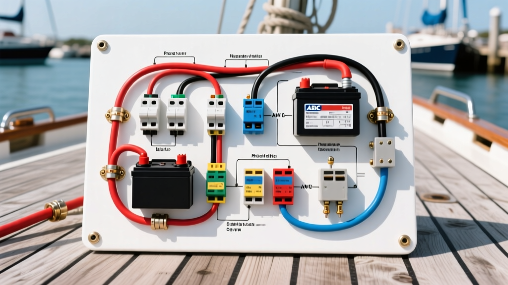
Decoding the Marine Basic 12 Volt Boat Wiring Diagram
Designing, upgrading, or troubleshooting a marine electrical system requires strict adherence to safety standards that far exceed typical automotive applications. The harsh marine environment—characterized by saltwater exposure, constant vibration, and high humidity—demands specialized components and precise routing. In this complete walkthrough, we will dissect a marine basic 12 volt boat wiring diagram tailored for a standard 16-foot center console outboard setup. This guide covers ABYC E-11 compliance, unswitched safety circuits, dual-battery management, and precise AWG sizing to prevent voltage drop and stray current corrosion.
Core Philosophy: Marine vs. Automotive Wiring
Before tracing the schematic, it is critical to understand why automotive wiring practices fail on the water. According to the American Boat & Yacht Council (ABYC), all marine DC wiring must utilize tinned, stranded copper wire (UL 1426 / SAE J1171). Untinned copper wicks moisture through capillary action, leading to internal oxidation and high-resistance failures. Furthermore, any electrical device installed in an enclosed engine compartment (such as a bilge blower or battery switch) must meet USCG 33 CFR 183.410 ignition protection standards to prevent the ignition of trapped fuel vapors.
Step-by-Step Diagram Walkthrough: 16ft Center Console Setup
Our reference diagram models a single-engine outboard center console featuring a dual-battery bank (one starting, one house), an automatic bilge pump, LED navigation lights, and a switch panel for accessories (VHF, GPS, stereo). We will trace the current from the source to the load across three primary circuit paths.
Path 1: The Unswitched Bilge Pump Circuit (Critical Safety)
The most common and dangerous mistake in basic boat wiring diagrams is routing the bilge pump through the main battery switch. If the battery switch is turned to 'OFF' while the boat is moored, a failing through-hull fitting or heavy rain will sink the vessel.
- Routing: The positive lead from the Rule 500 GPH bilge pump (drawing approx. 2.5A) runs directly to the positive post of the House Battery (Battery 2).
- Protection: An inline ATC blade fuse holder with a 5A fuse is installed within 7 inches of the battery terminal, per ABYC E-11.12.1.2.1.
- Switching: The positive wire then passes through a manual toggle switch at the helm (Dark Blue wire per ABYC), and finally to the float switch at the bilge. This allows both automatic operation via the float switch and manual override from the helm.
- Grounding: The negative lead (Black) returns to the house battery's negative bus bar, never to the engine block.
Path 2: Battery Bank and Main Distribution
For a dual-battery setup, the diagram utilizes a 1-2-BOTH-OFF rotary battery switch (e.g., Blue Sea Systems e-Series).
- Source Cables: Both the Starting Battery (Battery 1) and House Battery (Battery 2) feed into the switch using 1/0 AWG tinned copper battery cables with 3/8-inch ring terminals.
- Main Breaker: The common output from the battery switch routes to a 100A main DC circuit breaker mounted on the positive distribution bus. This protects the main feeder cable running to the helm DC breaker panel.
- House Loads: The helm panel (e.g., Blue Sea ST 6-Circuit) distributes power to switched accessories. Each circuit is protected by a thermal magnetic breaker sized 20% above the continuous load draw.
Path 3: Navigation Lights and 3% Voltage Drop Rules
Navigation lights are safety-critical and require a maximum 3% voltage drop. Assuming a 20-foot round-trip wire run from the helm panel to the stern light, and an LED load of 0.5A, standard 16 AWG wire is sufficient. However, if running incandescent bulbs drawing 2.5A over a 30-foot round trip, the diagram mandates stepping up to 10 AWG wire to maintain the 3% threshold.
ABYC E-11 Marine DC Wire Color Code Standards
Consistent color coding is vital for troubleshooting and preventing catastrophic reverse-polarity connections. Below is the mandated color schedule for our diagram's DC circuits.
| Circuit Function | ABYC Color Code | Diagram Application |
|---|---|---|
| DC Positive (General) | Red | Main battery feeds, accessory positive |
| DC Negative / Ground | Black or Yellow | All return paths to negative bus bar |
| Navigation Lights | Dark Blue | Stern light, bow combo light feeds |
| Bilge Blower / Pump | Brown | Bilge pump positive, blower motor positive |
| Starting Motor / Alternator | Yellow with Red Stripe | Alternator output to starter solenoid |
| Oil Pressure Sender | Light Blue | Engine harness to helm gauge |
Wire Sizing and Voltage Drop Specifications
Undersized marine wire causes excessive voltage drop, resulting in dim lights, slow windlass motors, and overheated insulation. The following chart dictates the minimum AWG required based on a 12V system, a 3% voltage drop tolerance, and a 15A maximum load.
| Round-Trip Wire Length | 5 Amp Load (e.g., LED Lights) | 10 Amp Load (e.g., VHF, Stereo) | 15 Amp Load (e.g., Windlass, Livewell) |
|---|---|---|---|
| 10 Feet | 16 AWG | 12 AWG | 10 AWG |
| 20 Feet | 14 AWG | 10 AWG | 8 AWG |
| 30 Feet | 12 AWG | 8 AWG | 6 AWG |
| 40 Feet | 10 AWG | 6 AWG | 4 AWG |
Note: For non-critical cabin lighting or bait pumps, a 10% voltage drop is permissible, allowing for one AWG size reduction. Always refer to the West Marine Wire Size Chart for exact calculations based on specific insulation temperature ratings.
Termination, Torque, and Corrosion Prevention
A flawless wiring diagram is useless if the physical terminations fail. Marine environments accelerate galvanic and electrolytic corrosion at connection points. Follow these expert termination protocols:
- Connector Selection: Never use standard vinyl-insulated crimp connectors. Use marine-grade, adhesive-lined heat-shrink solder-seal terminals (e.g., Ancor or GT Elektrik). The internal solder melts to form a gas-tight metallurgical bond, while the outer polyolefin shrink tube seals out moisture.
- Crimping Tool: Use a ratcheting hex-crimp tool designed for insulated terminals to ensure uniform deformation without piercing the heat shrink prematurely.
- Torque Specifications: Battery terminal nuts and bus bar studs must be torqued to manufacturer specifications to prevent arcing and thermal runaway. For standard 5/16-inch stainless steel battery studs, torque to 7-9 ft-lbs. For 3/8-inch studs, torque to 10-13 ft-lbs. Always use a split-ring lock washer or a Nord-Lock washer to combat engine vibration.
- Dielectric Grease: After torquing, coat the entire terminal and lug assembly with a heavy coat of marine dielectric grease or battery terminal protector spray to displace oxygen and salt spray.
Troubleshooting Common Marine 12V Faults
When the physical installation deviates from the basic boat wiring diagram, specific symptoms emerge. Use this decision tree to diagnose issues:
- Symptom: Bilge pump runs manually from the helm but not automatically via the float switch.
- Cause: The float switch ground is tied to the engine block instead of the house negative bus, or the float switch contacts are corroded.
- Fix: Reroute float switch ground to the main DC negative bus bar. Clean or replace the float switch.
- Symptom: VHF radio shuts off or displays 'Low Voltage' when transmitting.
- Cause: Transmitting draws up to 6A-8A instantaneously. If wired with 16 AWG over a long run, voltage drop exceeds the radio's low-voltage cutoff.
- Fix: Upgrade the VHF positive and negative feed to 10 AWG and ensure it is connected directly to the battery distribution posts, not daisy-chained off a stereo circuit.
- Symptom: Rapid depletion of the house battery while moored.
- Cause: Parasitic draw from solid-state electronics (stereo memory, GPS standby) or a failing diode in the alternator.
- Fix: Disconnect the negative battery cable and insert a digital multimeter set to Amps in series. Pull breakers one by one to isolate the parasitic draw circuit. If draw persists with all breakers off, inspect the alternator rectifier.
Summary and Best Practices
A properly executed marine basic 12 volt boat wiring diagram is the backbone of vessel safety and reliability. By separating unswitched safety loads (bilge pumps) from switched house loads, strictly adhering to ABYC color codes, and calculating AWG sizes based on a 3% voltage drop limit, you eliminate the vast majority of on-water electrical failures. Always label both ends of every wire using a marine heat-shrink label printer, and keep a laminated copy of your specific vessel's schematic in the helm console for emergency troubleshooting. For further reading on marine electrical safety and compliance, consult the BoatUS Wiring Basics Guide and your local ABYC-certified marine electrician.