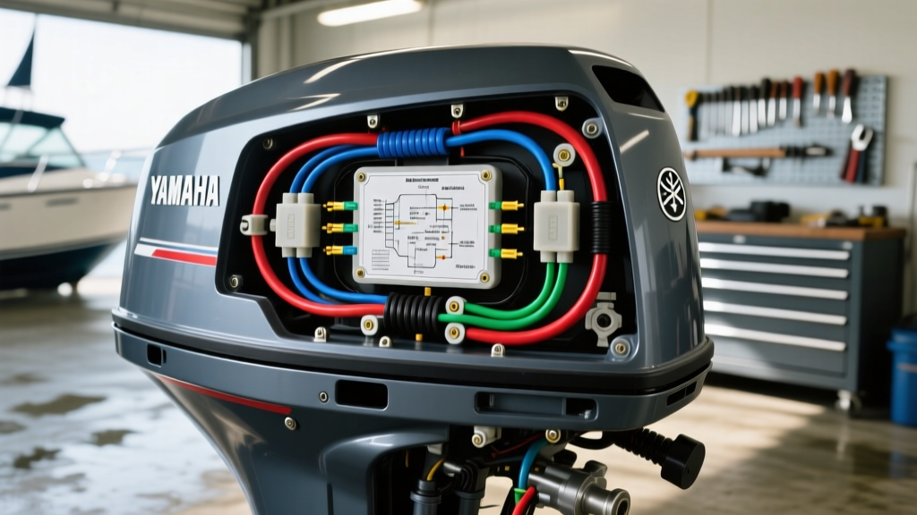
Introduction to Yamaha Marine Electrical Rigging
Rigging a Yamaha outboard motor requires a meticulous understanding of marine electrical systems. Unlike automotive applications, the marine environment demands strict adherence to corrosion-resistant materials, specific voltage drop tolerances, and waterproof connector protocols. Whether you are rigging a Yamaha F150 four-stroke or a classic 115HP two-stroke, interpreting Yamaha outboard wiring diagrams is the foundational step to ensuring reliable starting, accurate instrumentation, and safe operation on the water.
This practical how-to guide walks you through the physical installation and electrical termination of a Yamaha outboard main harness, translating schematic symbols into real-world marine wiring tasks. We will cover primary battery cable routing, ignition switch pinouts, analog gauge integration, and advanced troubleshooting techniques.
Decoding the Yamaha Outboard Wiring Diagrams
Yamaha service manuals typically separate electrical schematics into two distinct categories: the Engine-Side Sub-Harness and the Boat-Side Main Harness. The engine-side harness is largely pre-assembled, sealed, and utilizes proprietary waterproof connectors that plug directly into the ECU (Engine Control Unit) or CDI (Capacitor Discharge Ignition) module. As a rigger, your primary focus is the boat-side main harness, which bridges the engine to the helm, battery bank, and instrument cluster.
Historically, Yamaha utilized a 14-pin or 18-pin circular rubber connector for analog and early digital setups. Modern Command Link and NMEA 2000 systems use specialized CAN bus cabling, but the fundamental power, ground, and ignition routing remain consistent. According to the ABYC E-11 Electrical Standards, all boat-side wiring must be marine-grade, stranded, tinned copper wire to resist galvanic corrosion and vibration fatigue.
Step 1: Routing and Terminating Primary Power Cables
Before connecting the delicate multi-pin harnesses, you must establish a robust primary power and ground network. Yamaha outboards draw massive inrush current during cranking—often exceeding 150 amps for larger V6 models.
Selecting the Correct AWG
For battery cable runs under 15 feet (round trip), 1/0 AWG marine tinned copper is the minimum requirement for engines up to 200HP. For runs exceeding 15 feet, or for twin-engine setups sharing a house bank, step up to 2/0 AWG to mitigate voltage drop. The ABYC mandates that voltage drop on cranking circuits must not exceed 10% of the system voltage.
Termination and Torque Specifications
- Stripping and Crimping: Strip the insulation precisely to the depth of the terminal barrel. Use a heavy-duty hex crimp tool to compress the terminal, ensuring a gas-tight connection.
- Sealing: Apply 3M Marine Adhesive Sealant 5200 or use adhesive-lined marine heat shrink tubing over the crimp joint to prevent moisture wicking into the copper strands.
- Engine Block Ground: The main ground cable must attach directly to the outboard's designated grounding boss on the powerhead or engine bracket. Clean the mating surface to bare metal, apply a thin layer of dielectric grease after tightening, and torque the 8mm stainless steel hardware to 15-18 Nm (11-13 lb-ft).
Step 2: Rigging the Ignition and Emergency Shutoff
The helm-side ignition switch and emergency engine shutoff (lanyard) switch are critical safety components. Miswiring these circuits can result in a no-start condition or, worse, an inability to kill the engine in an emergency.
Yamaha standard 6-pin ignition switches follow a specific terminal layout:
- Terminal B (Battery): Connect to a switched 12V source from the main breaker panel (14 AWG Red wire).
- Terminal I (Ignition): Connect to the White wire on the main harness. This energizes the ECU and fuel pumps.
- Terminal S (Start): Connect to the Yellow/Red wire. This engages the starter solenoid.
- Terminal C (Choke/Primer): Connect to the Yellow wire (applicable primarily to older EFI or carbureted models).
- Terminals M & G (Magneto/Ground): These are tied to the Black/Yellow kill wire. When the key is turned to OFF, or the lanyard is pulled, M and G short together, grounding the ignition coils and stopping the engine.
Step 3: Connecting the Analog Instrument Cluster
While digital networks are prevalent, analog gauges remain popular for their redundancy and ease of troubleshooting. When referencing Yamaha outboard wiring diagrams for analog gauges, you will map the main harness outputs directly to the gauge studs.
| Gauge Type | Harness Wire Color | Signal Type / Function |
|---|---|---|
| Tachometer | Brown | AC Pulse from Stator/Rectifier |
| Speedometer | Green | Water Pressure (Pitot Tube) |
| Fuel Level | Pink | Variable Resistance (0-190 Ohm) |
| Voltmeter | Red / Black | Direct 12V DC Reference |
| Water Temp | Green/White | Variable Resistance (Sender Dependent) |
| Trim Gauge | Light Green / Blue | Variable Resistance (Trim Sender) |
Pro Tip: Always install a dedicated 5-amp inline fuse on the 12V positive feed (Red wire) supplying the instrument cluster illumination and internal circuitry.
Yamaha 14-Pin Main Harness Connector Pinout Reference
The cornerstone of Yamaha outboard rigging is the 14-pin circular connector. Below is the standard pinout configuration used across many Yamaha F-series and older two-stroke models. Always verify against the specific schematic in your Yamaha Outboard Parts Catalog service manual, as variations exist for multi-engine configurations.
| Pin Number | Wire Color | Function / Circuit |
|---|---|---|
| 1 | Red | Battery Positive (+12V Constant) |
| 2 | Black | Main Ground (-12V) |
| 3 | Brown | Tachometer Signal |
| 4 | Green | Speedometer Signal (Water Pressure) |
| 5 | Pink | Fuel Tank Sender Signal |
| 6 | Yellow | Choke / Primer Solenoid |
| 7 | White | Ignition / Run (ECU Power) |
| 8 | Yellow/Red | Starter Solenoid Engage |
| 9 | Black/Yellow | Magneto Stop / Kill Circuit |
| 10 | Orange | Warning Alarm / Overheat Buzzer |
| 11 | Light Green | Trim Relay (Up) |
| 12 | Blue | Trim Relay (Down) |
| 13 | White/Red | Accessory / Gauge Power |
| 14 | Black/White | Spare / Secondary Ground |
Advanced Troubleshooting and Voltage Drop Testing
Even with perfect adherence to Yamaha outboard wiring diagrams, marine environments introduce variables like hidden corrosion and vibration-induced micro-fractures. When diagnosing a no-crank or erratic gauge issue, avoid simply replacing parts. Instead, perform a voltage drop test.
Troubleshooting Decision Tree: Erratic Tachometer Signal
- Symptom: Tachometer needle bounces or reads zero at WOT (Wide Open Throttle).
- Step 1: Check the Brown wire connection at the 14-pin harness. Is there green copper oxide? Fix: Clean and re-crimp with marine heat shrink.
- Step 2: Measure AC voltage between the Brown wire and a known good ground while cranking. Reading should be >2V AC. If 0V, the stator or rectifier/regulator on the engine side is faulty.
- Step 3: Verify the tachometer's rear dip-switch settings. Yamaha outboards require specific pole settings (usually 6-pole for most 4-strokes). Fix: Adjust switches to match engine alternator pole count.
Troubleshooting Decision Tree: Intermittent Loss of Power to Helm
- Symptom: Gauges and ignition switch lose power when hitting waves.
- Step 1: Inspect the main 30-amp fuse holder near the battery. Vibration often causes cheap automotive fuse holders to lose tension. Fix: Replace with an ABYC-compliant marine fuse block with positive locking tabs.
- Step 2: Perform a voltage drop test on the Red (Pin 1) wire from the battery to the ignition switch 'B' terminal while wiggling the harness. A drop greater than 0.2V indicates a high-resistance fault inside the wire insulation. Fix: Pull a new 10 AWG marine-grade Red wire.
For comprehensive marine electrical safety protocols and best practices regarding overcurrent protection, refer to the BoatUS Outboard Wiring Basics guide. Properly executing these rigging steps ensures your Yamaha outboard will perform reliably, whether you are idling through a no-wake zone or pushing hard across open water.