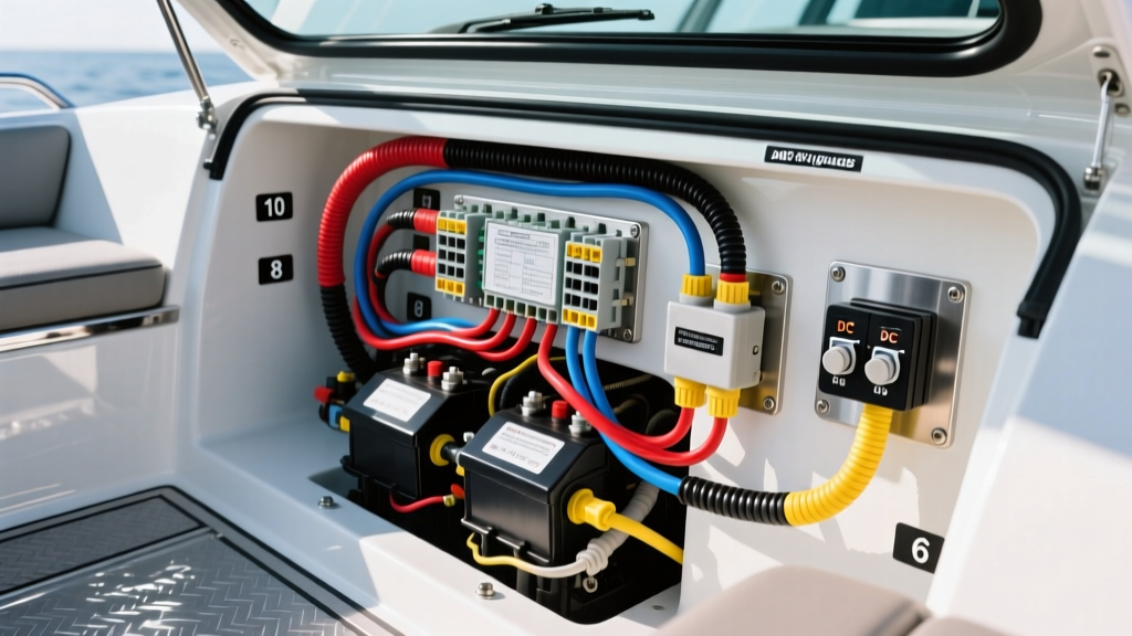
Project Scope: Architecting the Dual-Battery System
Upgrading a vessel from a single-battery configuration to a dual-battery system is one of the most critical modifications a boat owner can undertake. Whether you are powering a high-draw windlass, an extensive live-well pump network, or a modern suite of NMEA 2000 electronics, relying on a precise marine wiring diagram is non-negotiable. Winged installations lead to parasitic draws, catastrophic voltage drops, and potentially lethal DC electrical fires. This project guide walks you through drafting, calculating, and executing a custom marine wiring diagram for a dual-battery upgrade, ensuring your house bank never compromises your engine's starting battery.
Isolating the House and Starting Banks
The core objective of this upgrade is to separate the 'Starting Battery' (Cranking) from the 'House Battery' (Deep Cycle/AGM/Lithium). Your custom marine wiring diagram must integrate a Voltage Sensitive Relay (VSR) or an Automatic Charging Relay (ACR). When the engine is running and the alternator output exceeds 13.0V, the VSR closes, combining the banks to charge both simultaneously. When the engine stops and voltage drops below 12.8V, the VSR opens, isolating the starting battery from house loads. Drafting this logic into your schematic before cutting a single wire prevents alternator burnout and ensures reliable engine cranking.
Phase 1: Load Calculation and AWG Sizing
Before drawing your schematic, you must audit your DC loads. The American Boat & Yacht Council (ABYC) standard E-11 mandates that wire sizing be based on the maximum expected load and the total round-trip circuit length to maintain a voltage drop below 3% for sensitive electronics and 10% for general loads.
Load Audit and Wire Sizing Table
| Device / Load | Max Draw (A) | Round-Trip Length (ft) | Required AWG (3% Drop) | Fuse / Breaker Rating |
|---|---|---|---|---|
| Electric Windlass | 120A (Surge) | 35 ft | 2/0 AWG | 150A ANL |
| Chartplotter / Sonar | 4.5A | 20 ft | 14 AWG | 5A Blade |
| Bilge Pump (Auto) | 5.0A | 24 ft | 14 AWG | 7A Blade |
| Cabin LED Lighting | 8.0A | 30 ft | 12 AWG | 10A Blade |
| VHF Radio (Transmit) | 6.0A | 18 ft | 14 AWG | 10A Blade |
Note: Always size the overcurrent protection device (OCPD) based on the smallest wire AWG in the circuit, not the maximum draw of the device.
Phase 2: Drafting the Marine Wiring Diagram
A professional marine wiring diagram utilizes standardized symbols to map the flow of DC current from the battery banks to the distribution bus bars, and finally to the loads. When drafting your schematic, incorporate the following critical nodes:
- Main Battery Fuses (MRBF): Place an MRBF (Main Battery Fuse) directly on the positive terminal of each battery bank. This protects the primary un-fused positive cables running to the distribution panels in the event of a dead short.
- Shunt Placement: If installing a battery monitor (e.g., Victron SmartShunt), your diagram must route all negative house loads through the shunt's load side. The only exception is the negative cable returning to the starter motor and the alternator ground.
- Bus Bar Distribution: Utilize dual-stud or multi-stud tin-plated copper bus bars. Diagram the positive bus bar with a cover to prevent accidental shorting with dropped tools.
Standard ABYC E-11 DC Color Codes
Your marine wiring diagram must specify jacket colors to ensure future troubleshooting is seamless. Adhere strictly to ABYC color standards:
- Yellow: DC Negative / Ground Return
- Red: DC Positive (Unswitched, directly from battery/bus)
- Orange: DC Positive (Switched via ignition or distribution panel)
- Blue: Cabin and Navigation Lighting
- Black: Alternator output or specific OEM harnesses (Avoid using black for DC negative in marine environments to prevent confusion with AC Black/Hot wiring).
Phase 3: Execution, Termination, and Routing
Translating your marine wiring diagram into physical reality requires marine-grade materials. Never use automotive-grade (untinned) wire in a marine environment. You must use Type III stranding, tinned copper wire (UL 1426 / SAE J1128) to resist saltwater corrosion and capillary action wicking. Resources like the Pacer Group provide excellent marine-specific wire and terminal specifications.
Crimping and Heat Shrink Protocols
Soldering is generally discouraged in high-vibration marine environments because it creates a rigid point that can fatigue and snap under engine vibration. Instead, use ratcheting crimpers calibrated for the specific AWG. Follow this termination sequence:
- Strip the wire jacket using precision strippers to avoid nicking the tinned copper strands.
- Slide a piece of 3:1 adhesive-lined polyolefin heat shrink (e.g., 3M FP-301) over the wire.
- Insert the wire into the brass barrel of the ring terminal and crimp using a ratcheting tool until the die releases.
- Slide the heat shrink over the barrel so it covers the insulation and half the barrel. Apply heat until the adhesive sealant purges slightly from the edges, creating a waterproof environmental seal.
Torque Specifications for Marine Bus Bars
Under-torqued connections create high-resistance hotspots, while over-torqued connections can snap studs or deform ring terminals. When securing 3/8-inch or 5/16-inch stainless steel studs on your distribution bus bars, use an inch-pound torque wrench:
- 5/16-inch Stud: 50 to 60 in-lbs
- 3/8-inch Stud: 70 to 80 in-lbs
- 1/2-inch Stud (e.g., 2/0 AWG Windlass Lugs): 120 to 140 in-lbs
Phase 4: Voltage Drop Testing and Troubleshooting
Once the physical installation matches your marine wiring diagram, you must validate the system under load. A multimeter is your primary diagnostic tool. Set the multimeter to DC Volts. Place the red probe on the positive battery terminal and the black probe on the positive terminal of the load (e.g., the windlass motor) while the device is actively running. Any reading above 0.36V on a 12V system indicates a failing connection, undersized wire, or corroded terminal.
Symptom-Cause-Fix Decision Tree
Use this troubleshooting matrix to diagnose common dual-battery upgrade failures:
- Symptom: House battery drains overnight despite all switches being 'OFF'.
- Cause: Parasitic draw from an improperly wired bilge pump float switch or a faulty VSR that remains closed.
- Fix: Verify the bilge pump is wired directly to the unswitched side of the house bus bar with its own inline fuse, bypassing the main house disconnect. Test the VSR with a multimeter; it should show infinite resistance (open) when the resting voltage is below 12.8V.
- Symptom: Chartplotter reboots when the VHF radio keys up to transmit.
- Cause: Severe voltage drop on the shared positive or negative bus bar due to undersized feeder cables from the battery bank.
- Fix: Upgrade the main feeder cables from the house battery to the distribution bus bars. If the diagram specifies 4 AWG but the bus bars are drawing 40A+ cumulative, upgrade the main feeders to 2 AWG or 1 AWG to reduce resistance.
- Symptom: Alternator whine or high-pitched noise in the stereo head unit.
- Cause: Ground loop caused by the stereo and the alternator sharing the same negative bus bar return path, or using the engine block as a negative return for sensitive electronics.
- Fix: Re-route the stereo's DC negative wire directly to the main house battery negative terminal or a dedicated, isolated negative bus bar, completely bypassing the engine block ground.
Final Inspection and Documentation
The final step of any professional marine modification project is updating the physical documentation. Print your finalized marine wiring diagram on waterproof paper, laminate it, and store it in the vessel's manual sleeve. Label every wire at both the source and the termination point using heat-shrink cable markers. By adhering to ABYC standards, utilizing proper AWG calculations, and executing meticulous terminations, your dual-battery upgrade will provide reliable, safe power for years of offshore navigation.