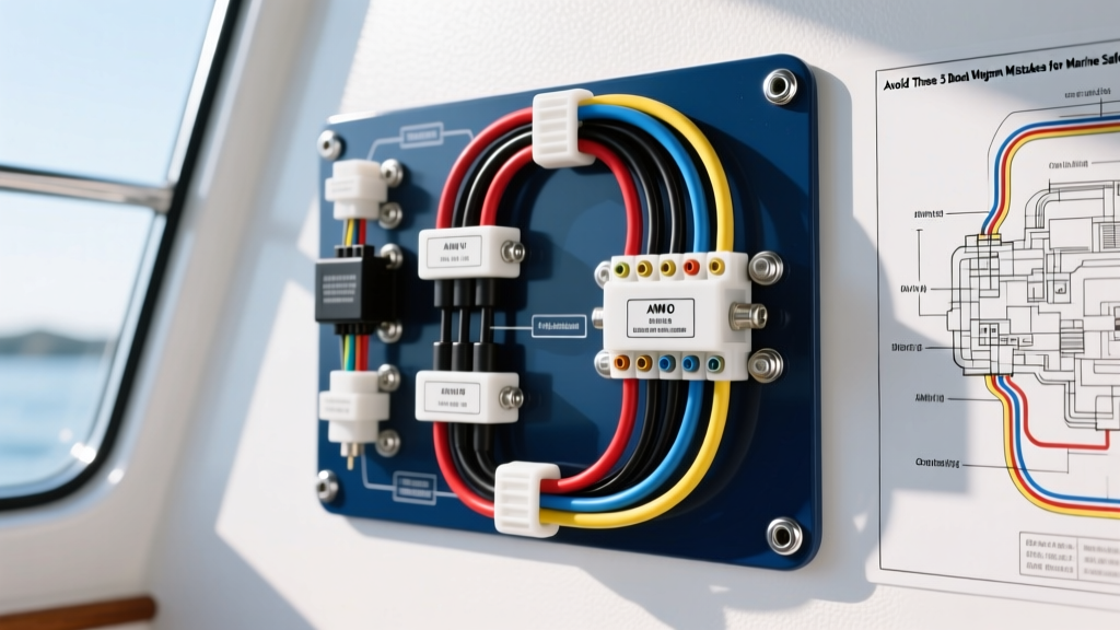
The Hidden Dangers of Misinterpreting a Boat Wiring Diagram
Reading a boat wiring diagram is only the first step in building or repairing a marine electrical system. Unlike automotive environments, marine vessels are subjected to constant vibration, high humidity, saltwater corrosion, and the ever-present risk of igniting trapped bilge fumes. A diagram might show you where the wires go, but it rarely warns you about the specific marine-grade materials, ABYC (American Boat & Yacht Council) compliance codes, and ignition protection standards required to keep your vessel from catching fire or sinking.
As marine electrical systems grow more complex with lithium battery banks, digital switching, and high-amperage bow thrusters, the margin for error shrinks. Below, we break down the most critical boat wiring diagram mistakes, safety warnings, and technical specifications that every marine electrician and DIY boat owner must know.
Mistake 1: Using Automotive Wire (SAE J1128) Instead of Marine Wire (UL 1426)
The most common and dangerous mistake occurs before the first crimp is made: using standard automotive wire found in big-box auto parts stores. Automotive wire is manufactured to SAE J1128 standards, which dictates thicker, fewer copper strands and an untinned surface. In a marine environment, untinned copper rapidly oxidizes, forming black copper oxide. This oxide acts as an insulator, increasing resistance, generating excess heat, and eventually causing a voltage drop or an electrical fire.
The Safety Fix: You must use marine-grade wire certified to UL 1426 or SAE J1127. Marine wire features Type 3 fine stranding (up to 65% more strands than automotive wire of the same AWG), making it highly resistant to engine vibration. Furthermore, every individual copper strand is hot-dipped in tin to prevent galvanic corrosion and capillary wicking of moisture.
Mistake 2: Miswiring the Bilge Pump and Float Switch
Many generic wiring diagrams incorrectly route the bilge pump and float switch through the main DC breaker panel. If the vessel's main battery disconnect switch is turned to the 'OFF' position while docked, the bilge pump loses power. If a heavy rainstorm occurs or a fitting leaks, the boat will sink at the slip.
The 7-Inch Fuse Rule and 24/7 Power
According to ABYC E-11 standards, bilge pumps must be wired to a continuous, unswitched 24/7 power source. This is typically achieved by wiring directly to the positive terminal of the battery bank or to a dedicated, always-hot fused busbar.
- Wire Color: Use Brown for the DC positive feed to the float switch, and Brown with a black tracer for the switch-to-pump run.
- Overcurrent Protection: An inline fuse or circuit breaker must be installed on the positive conductor. Crucially, this fuse must be placed within 7 inches of the battery positive terminal. If the 7-inch rule cannot be met, the wire must be enclosed in a continuous protective sheath (like split loom) up to the fuse location to prevent a dead short against the engine block.
- Ignition Protection: Any fuse, breaker, or relay located in the engine compartment or bilge must be certified to SAE J1171 (Ignition Protected) to prevent sparking in the presence of gasoline fumes.
Mistake 3: Ignoring ABYC E-11 Color Codes
Automotive wiring often uses black for ground and random colors for positive feeds. In marine applications, using the wrong color code can lead to catastrophic misdiagnoses during emergency troubleshooting. ABYC E-11 mandates strict color-coding for DC systems to ensure safety and standardization.
| Color | Application / Function |
|---|---|
| Black or Yellow | DC Grounding / Negative Return |
| Red | Unfused DC Positive (Battery to main switch) |
| Brown | Fused DC Positive (General accessories, bilge pumps) |
| Blue | Navigation Lights |
| Yellow with Red Tracer | Starting Motor Positive |
| Dark Green | DC Bonding / Grounding System |
Source reference: Marine How To - ABYC Wiring Standards
Mistake 4: Sizing Wire for Ampacity Only (Ignoring Voltage Drop)
A standard automotive boat wiring diagram might specify 10 AWG wire for a 15-amp navigation light circuit. While 10 AWG wire will safely carry 15 amps without melting (ampacity), it fails to account for voltage drop over long cable runs. Navigation lights and sensitive marine electronics require a maximum voltage drop of 3%. Non-critical loads (like cabin lights or bilge pumps) allow for a 10% drop.
If you run a 40-foot round-trip circuit to a stern navigation light using 10 AWG wire at 15 amps, you will experience a voltage drop of over 1.5V. This leaves only 10.5V at the fixture, severely dimming the light and violating US Coast Guard visibility requirements.
Marine Voltage Drop & AWG Sizing Chart (12V System, 3% Drop)
Use this reference chart to properly size wire for critical 3% drop circuits (Navigation Lights, GPS, Chartplotters, VHF Radios). Values represent maximum one-way wire length in feet.
| Current (Amps) | 14 AWG | 12 AWG | 10 AWG | 8 AWG | 6 AWG |
|---|---|---|---|---|---|
| 5A | 11 ft | 18 ft | 29 ft | 46 ft | 73 ft |
| 10A | 5 ft | 9 ft | 14 ft | 23 ft | 36 ft |
| 15A | 3 ft | 6 ft | 9 ft | 15 ft | 24 ft |
| 20A | 2 ft | 4 ft | 7 ft | 11 ft | 18 ft |
For exact calculations on complex runs, utilize the Blue Sea Systems Circuit Wizard to factor in specific insulation temperature ratings and bundling derations.
Mistake 5: Using the Engine Block as a DC Negative Return
In automotive applications, the steel chassis or engine block is frequently used as the negative ground return path to save wire. In a marine environment, this practice is strictly prohibited by ABYC standards for house accessories. Relying on the engine block for DC negative returns introduces stray current corrosion, creates unpredictable voltage drops across engine mounts, and complicates troubleshooting.
The Safety Fix: Every DC accessory must have a dedicated negative return wire (Black or Yellow) routed back to a centralized, marine-grade negative busbar. The negative busbar is then connected to the battery negative terminal. The only exception to this rule is the engine starter motor and engine-mounted alternator, which may ground directly to the engine block due to the massive amperage involved (often exceeding 200A during cranking), provided the engine block is bonded to the DC negative bus via a heavy-gauge (e.g., 2/0 AWG) grounding strap.
Mistake 6: Failing to Use Adhesive-Lined Heat Shrink Terminations
Standard vinyl-insulated crimp connectors are a liability on a boat. Vibration causes the metal crimp barrel to loosen slightly, allowing humid, salty air to enter the connection. Over time, this creates a high-resistance fault. Furthermore, standard heat shrink does not seal the wire entry point, allowing moisture to wick under the insulation via capillary action.
The Safety Fix: Only use adhesive-lined (dual-wall) marine heat shrink terminals. When heated, the inner layer of thermoplastic adhesive melts and flows around the wire strands and the insulation jacket, creating a 100% waterproof, strain-relieved seal. Always use a calibrated ratcheting crimp tool designed for insulated terminals to ensure the correct compression ratio without cutting the copper strands.
Final Safety Checklist for Marine Wiring
Before energizing any new circuit derived from your boat wiring diagram, verify the following:
- Overcurrent Protection: Is the fuse/breaker sized correctly for the smallest AWG wire in the circuit?
- Ignition Protection: Are all bilge-mounted components (fuses, relays, blowers) SAE J1171 certified?
- Chafe Protection: Are all wires passing through metal bulkheads protected by rubber grommets or clamshell ducts?
- Support: Are cables secured with UV-resistant, stainless-steel cushion clamps every 18 inches to prevent vibration fatigue?
- Drip Loops: Are wires entering electrical panels or junction boxes routed with a drip loop to prevent water from running down the wire into the connection?
By treating a boat wiring diagram as a baseline rather than an absolute rulebook, and by strictly adhering to ABYC material and safety standards, you ensure your vessel's electrical system remains reliable, efficient, and safe in the harshest marine environments.