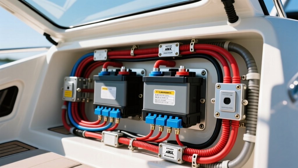
Decoding the Hurricane Deck Boat Wiring Diagram Architecture
Godfrey Marine’s Hurricane deck boats are renowned for their expansive layouts and versatile water sports capabilities, but their underlying DC electrical systems can be notoriously complex to troubleshoot. Whether you are working with an older analog Carling switch panel or a newer CZone digital switching architecture, understanding the core Hurricane deck boat wiring diagram is critical for safe modifications and accurate diagnostics. Unlike automotive systems that rely on a steel chassis for ground returns, marine DC systems must utilize dedicated, insulated ground return wires routed back to a central negative bus bar. This guide provides an advanced technical deep dive into the harness routing, distribution topology, and ABYC-compliant specifications required to maintain and upgrade a Hurricane deck boat’s electrical infrastructure.
Main Harness Routing and Rigging Tube Integrity
In most Hurricane models (particularly the SD 2200 through 2400 series), the primary wiring harness originates at the helm distribution panel and travels aft through the starboard-side rigging tube. This corrugated PVC or HDPE tube also houses hydraulic steering lines, fuel primer bulbs, and throttle/shift cables. A common failure mode in deck boats is harness chafing where the loom rubs against hydraulic fittings or sharp fiberglass edges inside the tube. When tracing a short circuit or an open ground in your Hurricane deck boat wiring diagram, always inspect the starboard rigging tube entry and exit points. Factory harnesses should be wrapped in split-loom tubing and secured with anti-chafe tape (such as 3M Temflex or Tesa 51036) every 18 inches to prevent insulation degradation from vibration and moisture intrusion.
Dual-Battery Isolation and Distribution Block Topology
Because Hurricane deck boats frequently power high-draw accessories like wakeboard tower speakers, LED underwater lighting, and windlasses, a dual-battery setup is standard on most I/O and large outboard configurations. The factory wiring diagram typically integrates a Blue Sea Systems Dual Circuit Plus battery switch or an Automatic Charging Relay (ACR).
When upgrading or repairing the battery distribution block, you must adhere to strict AWG sizing to prevent voltage drop and thermal events. The main positive and negative battery cables must be, at minimum, 1/0 AWG for runs under 5 feet, and 2/0 AWG for runs exceeding 5 feet from the battery bank to the starter motor and main distribution bus. These cables must be marine-grade, tinned copper wire meeting UL 1426 or SAE J378 standards. Untinned automotive wire (SAE J1128) will rapidly succumb to galvanic corrosion in the humid, salt-rich environment of a deck boat bilge, leading to high-resistance connections that mimic a dead battery.
Hurricane DC Distribution Panel Pinout and Circuit Mapping
The central DC distribution panel, usually located beneath the helm console behind an access door, acts as the nerve center for the Hurricane deck boat wiring diagram. Below is a technical specification chart detailing standard circuit mapping, ABYC-compliant wire color codes, and AWG requirements for a typical Hurricane SD series analog switch panel.
| Circuit Function | Wire Color (ABYC E-11) | Wire Gauge (AWG) | Fuse/Breaker Rating | Switch Type |
|---|---|---|---|---|
| Navigation / Anchor Lights | Green with White Stripe | 14 AWG | 5A Blade | SPST Toggle (Illuminated) |
| Bilge Pump (Manual Override) | Brown | 12 AWG | 5A Blade | 3-Position (Off/Auto/On) |
| Engine Blower Motor | Yellow with Black Stripe | 14 AWG | 10A Blade | SPST Toggle |
| Stereo / Amplifier Memory | Yellow with Red Stripe | 16 AWG | 5A Blade | Unswitched (Direct to Bus) |
| Courtesy / Deck Lighting | Light Blue | 14 AWG | 10A Blade | Dimmer / PWM Module |
| Livewell Pump (Aft) | White with Green Stripe | 12 AWG | 10A Blade | SPST Toggle |
Accessory Circuit Breakdown: The Bilge Pump Anomaly
One of the most misunderstood aspects of the Hurricane deck boat wiring diagram is the bilge pump circuit. According to ABYC E-11 standards, the automatic bilge pump circuit must be wired directly to the battery positive terminal via an inline fuse, completely bypassing the main helm battery switch and the primary DC distribution breaker. This ensures that if the boat is moored and the main battery switch is turned to the 'OFF' position, the float switch can still activate the pump to prevent sinking.
In Hurricane factory harnesses, you will typically find a 12 AWG brown wire running from the inline fuse near the battery to the bilge float switch, and then to the pump motor. The manual override function at the helm is fed from the switched side of the distribution panel. When troubleshooting a bilge pump that runs continuously and drains the battery, the fault rarely lies in the pump motor itself. Instead, inspect the float switch for debris binding the mechanical arm, or test the brown manual-override wire for a short to ground inside the helm switch housing, which is a frequent victim of spilled beverages and rain ingress.
Advanced Troubleshooting: Voltage Drop and Ampacity Derating
When modifying a Hurricane deck boat to add high-draw accessories like a windlass or a 1000W marine audio amplifier, relying solely on the physical fit of a wire is a critical error. Wire ampacity must be derated when bundled in engine compartments or enclosed rigging tubes where ambient temperatures exceed 50°C (122°F).
Use the Blue Sea Systems Circuit Calculator to determine the exact voltage drop. For example, running a 14 AWG wire to a 5A navigation light over a 25-foot round-trip distance yields a voltage drop of less than 3%, which is acceptable. However, running a 14 AWG wire to a 15A livewell pump over the same distance results in a 9% voltage drop. This severe drop causes the pump motor to draw excess amperage to compensate for the lack of voltage, leading to overheated windings and premature pump failure. Always size wire based on a maximum 3% voltage drop for critical electronics and a maximum 10% drop for non-critical lighting.
Connector Selection: Deutsch DT vs. Heat-Shrink Splices
The marine environment is hostile to standard electrical connections. The factory Hurricane harness relies heavily on multi-conductor marine cables (e.g., 14/7 or 16/5 tinned bundles) terminated at the helm with spade connectors. When extending these harnesses for aftermarket tower lights or radar arches, never use standard vinyl-insulated crimp connectors. The capillary action of stranded copper will wick moisture directly into the wire jacket, causing green copper oxide corrosion that travels feet up the harness.
For permanent splices, use adhesive-lined marine heat shrink (such as Ancor or 3M 4000 series) and a dedicated heat gun to ensure the inner meltable adhesive seals the wire jacket completely. For removable accessories, upgrade to Deutsch DT series or Weather-Pack connectors. These feature silicone rear seals and interlocking wedge locks that withstand the high-vibration environment of a deck boat planing across choppy water. Apply a small amount of dielectric grease to the pins before mating to prevent galvanic oxidation between dissimilar metals.
Summary of Best Practices for Hurricane Harness Maintenance
- Trace with a Tone Generator: Because Hurricane uses multi-conductor bundles where individual wire colors may fade or become indistinguishable in the bilge, use an inductive tone generator to trace circuits from the helm to the transom without piercing the wire insulation.
- Verify Ground Bus Integrity: A flickering stereo or dimming LED courtesy lights are rarely caused by a failing positive feed. Check the torque on the main negative bus bar located near the battery bank; loose set-screws on ground return wires cause high-resistance grounds that disrupt the entire DC network.
- Protect the Ignition Kill Circuit: The engine ignition and emergency kill lanyard circuits are highly sensitive. Ensure the purple (ignition) and black/yellow (kill) wires are routed away from high-tension spark plug wires to prevent electromagnetic interference (EMI) which can cause erratic tachometer readings or stalling.
By treating the Hurricane deck boat wiring diagram not just as a map, but as a dynamic system governed by marine-specific electrical physics, you can ensure reliable, safe, and ABYC-compliant performance on the water for years to come.