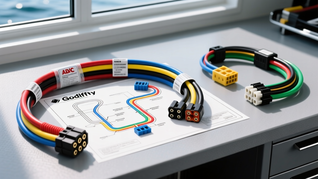
Decoding the Godfrey Pontoon Wiring Diagram
Whether you are restoring a classic Sanpan, upgrading a Sweetwater, or troubleshooting an Aqua Patio, interpreting a Godfrey pontoon wiring diagram is the first step toward a reliable marine electrical system. Godfrey Marine has historically utilized a centralized helm switch panel that routes a primary loom down the starboard chine to a stern junction block, branching off to navigation lights, bilge pumps, and aerators. However, as these vessels age, the OEM harnesses often suffer from capillary corrosion, voltage drop, and brittle insulation. This guide compares OEM replacement harnesses against custom ABYC-compliant aftermarket builds, helping you select the right components based on your specific schematic.
Harness Selection: OEM Replacement vs. Custom ABYC Build
When your factory diagram reveals degraded circuits, you face a critical selection: order a direct-fit OEM replacement from a Godfrey dealer or build a custom harness using premium marine-grade components. Direct OEM replacements offer plug-and-play convenience but often repeat the original manufacturer's cost-saving compromises, such as untinned copper wire and unsealed connectors. Conversely, building a custom harness based on the Godfrey schematic ensures strict adherence to ABYC E-11 AC & DC Electrical Systems on Boats standards.
| Feature | OEM Godfrey Replacement | Custom Build (Ancor + Blue Sea) | Pre-Loomed Universal (MarineTown) |
|---|---|---|---|
| Wire Material | Untinned Copper (Type GXL) | Tinned Copper (UL 1426) | Tinned Copper |
| Insulation | PVC (Standard) | PVC (Flexible, Heat Resistant) | PVC |
| Connectors | Molded Multi-Pin / Spade | Deutsch DT / Heat Shrink | Universal Bullet / Spade |
| ABYC Compliance | Partial (Model Year Dependent) | 100% Compliant | Varies by Kit |
| Best Application | Quick Resale / Minor Repair | Long-Term Restoration / Offshore | Budget Patch / Temporary Fix |
Wire Color Codes and ABYC E-11 Discrepancies
One of the most frustrating aspects of reading an older Godfrey pontoon wiring diagram (pre-2012) is the deviation from standard marine color codes. Historically, Godfrey frequently utilized black wire for DC ground. Under current ABYC E-11 standards, black is reserved for AC hot wires, while yellow (or yellow with a red stripe) is mandated for DC negative. If you are splicing into an existing Godfrey harness, always use a digital multimeter to verify continuity to the battery negative terminal before assuming black is ground.
| Circuit Function | OEM Godfrey Color (Pre-2012) | ABYC E-11 Standard Color | Recommended AWG | Breaker Rating |
|---|---|---|---|---|
| Main Panel Feed | Red | Red | 10 AWG | 30A |
| DC Ground Return | Black | Yellow | 10 AWG | N/A |
| Bow Nav Light | Brown | Brown | 14 AWG | 5A |
| Stern Nav Light | Green | Green | 14 AWG | 5A |
| Bilge Pump (Switched) | Blue | Blue | 12 AWG | 5A |
| Aerator Pump | White | White | 12 AWG | 5A |
Connector Selection for Under-Deck Runs
The Godfrey schematic typically shows a junction block or a series of butt splices near the transom where the main harness meets the stern light and bilge pump pigtails. OEM setups often rely on standard vinyl-insulated crimps or molded Molex connectors that trap moisture, leading to green corrosion (copper oxide) and high resistance.
Deutsch DT Series vs. OEM Molded Connectors
For any connection exposed to the bilge environment or exterior transom, upgrade to Deutsch DT series connectors. A 12-pin DT connector (Part # DT06-12S) is ideal for terminating the main Godfrey starboard loom at the stern junction. Unlike OEM molded plugs, Deutsch connectors feature silicone rear grommets that seal individual wires and a secondary wedge lock that prevents pins from backing out due to vibration. When crimping the solid nickel-plated pins for 14 AWG and 12 AWG tinned wire, use a ratcheting crimper calibrated for Deutsch contacts, ensuring the wire barrel is flush and the insulation grip bites the jacket without piercing it.
Upgrading the Main Switch Panel Breakers
Godfrey OEM switch panels frequently utilize thermal circuit breakers that are highly sensitive to ambient temperature. In a closed pontoon helm compartment on a 95-degree day, a 10A thermal breaker may trip at 8A simply due to heat soak, killing your navigation lights or bilge pump. When rebuilding your harness based on the diagram, replace the OEM panel with a Blue Sea Systems WeatherDeck panel featuring hydraulic-magnetic breakers. These breakers trip strictly on current overload, ignoring ambient temperature fluctuations, providing vastly superior reliability for critical marine circuits.
Bilge Pump Float Switch Wiring Nuances
A common error when reading the Godfrey pontoon wiring diagram is misinterpreting the bilge pump circuit. The bilge pump must be wired directly to the battery positive terminal via an inline fuse, bypassing the main ignition or house switch. This ensures the pump can activate via the float switch even when the boat is completely powered down and stored. According to ABYC standards, the inline ATC fuse holder must be installed within 7 inches of the battery positive terminal. Use 12 AWG Ancor tinned marine wire for this run to minimize voltage drop, ensuring the float switch receives the full 12.6V required to close the relay or directly power the pump impeller.
Troubleshooting Common Godfrey Harness Failures
Voltage Drop at the Aerator Pump
If your livewell aerator is humming but failing to push water, the pump motor is likely suffering from voltage drop. Godfrey's long starboard wire runs (often exceeding 25 feet from helm to stern) can drop voltage below 11V if 14 AWG wire was used at the factory. Use a multimeter to measure voltage at the pump terminals while the circuit is under load. If you read below 11.5V, upgrade the positive and negative runs to 12 AWG wire as specified in our custom build chart.
Navigation Light Ground Faults
Pontoon aluminum decks and extrusions are conductive, but they should never be used as a ground return path. Older Godfrey diagrams sometimes show navigation light bases grounding directly to the aluminum deck rail. This causes galvanic corrosion and intermittent light failures. Always run a dedicated yellow (ABYC) ground wire from every stern and bow light fixture back to the main negative bus bar, isolating the DC circuit from the aluminum hull.