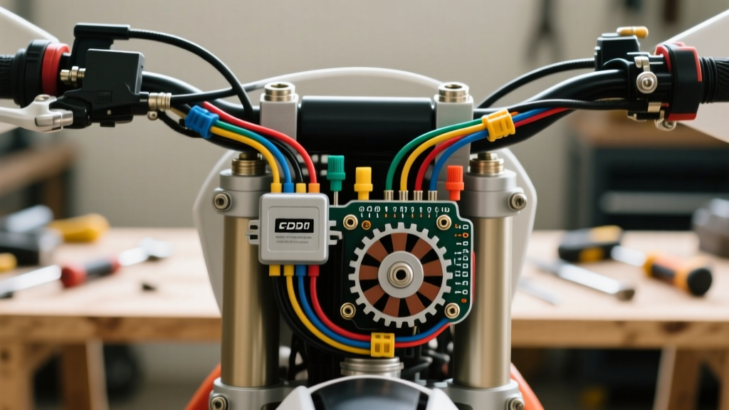
The Reality of Import Motorcycle Electrical Systems
When working with a Chinese dirt bike wiring diagram, the first rule of diagnostics is to abandon your preconceptions about standard Japanese or American color codes. Brands like SSR, Tao Motor, Apollo, and Pitster Pro utilize mass-produced, generic electrical components sourced from various regional suppliers. Consequently, a wire that is black/red on one production run might be white on the next. To successfully navigate these systems, you must trace the circuit logic rather than relying solely on the wire jacket color. This complete walkthrough dissects the standard AC-CDI architecture found on 110cc to 160cc horizontal and vertical clone engines, providing the exact pinouts, AWG specifications, and multimeter testing procedures required to map, repair, or rebuild your harness from scratch.
Core Architecture: AC vs. DC Ignition Systems
The vast majority of Chinese-manufactured off-road motorcycles utilize an AC (Alternating Current) ignition system. Unlike DC systems that rely on a 12V battery to feed the Capacitor Discharge Ignition (CDI) unit, an AC system generates its own high-voltage spark energy directly from a dedicated stator winding. This means the bike will run and spark even with a completely dead or disconnected battery. Understanding this distinction is critical; if you attempt to wire a DC CDI into a harness designed for an AC stator, you will instantly fry the CDI unit. According to Electrosport Industries tech articles, verifying the CDI type by checking the stator's source coil output is the mandatory first step in any import motorcycle electrical rebuild.
Step-by-Step Wiring Walkthrough
Phase 1: Stator to CDI Power Delivery
The ignition sequence begins at the stator plate located behind the left-side flywheel. The stator features two primary circuits: the ignition source coil and the lighting coil. The ignition source coil outputs a raw AC voltage ranging from 15V at idle to over 100V at high RPM. This wire (typically Black/Red or solid White) connects directly to the power input pin of the CDI. This circuit should be wired using 18 AWG stranded copper wire, compliant with SAE J1128 standards for low-tension primary cables, to minimize resistance while maintaining flexibility against engine vibration. The lighting coil (typically Yellow) routes to the voltage regulator/rectifier and is completely isolated from the ignition circuit.
Phase 2: The Pickup Coil and Timing Signal
Mounted just outside the flywheel is the pulse generator, or pickup coil. As the flywheel's timing tab passes the magnetic pickup, it induces a small voltage spike (usually 1-3V AC). This signal tells the CDI exactly when to fire. The pickup coil utilizes a two-wire setup on some models, but most Chinese dirt bikes use a single-wire shielded pickup where the shield acts as the ground. The signal wire (often White or Blue/White) routes to the CDI's trigger pin. Because this signal is highly susceptible to electromagnetic interference (EMI), it must never be routed parallel to the spark plug wire or the stator's high-voltage AC line.
Phase 3: CDI to Ignition Coil Discharge
Once the CDI receives the trigger signal, it dumps its stored capacitor voltage (up to 400V DC) into the primary winding of the ignition coil. The output wire from the CDI to the ignition coil is almost universally Black. The ignition coil steps this voltage up to 20,000-30,000 volts, sending it through the spark plug cap to the electrode. The primary side of the ignition coil requires a solid ground, typically achieved by bolting the coil's mounting tab directly to a clean, bare-metal section of the frame or engine block.
The Universal Chinese 5-Pin CDI Pinout Table
The 5-pin AC CDI is the undisputed standard for Chinese pit bikes and dirt bikes. While the plastic connector housing may vary, the internal pin logic remains remarkably consistent. Below is the definitive reference table for mapping your harness to the CDI.
| Pin Number | Function | Common Wire Colors | Recommended AWG | Multimeter Test (Key On) |
|---|---|---|---|---|
| 1 | Stator AC Power Input | Black/Red, White, Red | 18 AWG | 15-100V AC (Cranking/Running) |
| 2 | Pickup Coil Trigger | White, Blue/White, Green/White | 20 AWG (Shielded) | 0.5-3V AC (Cranking) |
| 3 | System Ground | Green, Black | 16 AWG | Continuity to Battery (-) |
| 4 | Kill Switch Input | Black/White, Black/Yellow | 18 AWG | Open (Run) / Ground (Kill) |
| 5 | Ignition Coil Output | Black, Yellow/Black | 16 AWG | DC Voltage Spike (Requires Peak-Hold) |
Kill Switch and Safety Circuit Logic
One of the most misunderstood aspects of the Chinese dirt bike wiring diagram is the kill circuit. Unlike modern fuel-injected motorcycles that use a positive 12V trigger to activate a relay and cut the fuel pump, AC CDI systems use a "ground-to-kill" logic. Pin 4 on the CDI is the kill input. When the handlebar kill switch or the key cylinder is turned to the "OFF" position, it physically bridges Pin 4 to the chassis ground (Pin 3). This instantly drains the CDI's capacitor and prevents it from firing the coil. If your bike has no spark, the most common culprit is a corroded kill switch internally shorting to ground, or a pinched harness wire bridging the Black/White kill wire to the frame. Always isolate the kill wire when diagnosing a no-spark condition.
Regulator/Rectifier and Lighting Circuit Walkthrough
While the ignition runs on AC, the lighting circuit and battery charging system require regulated DC or clipped AC. The Yellow wire from the stator carries raw, unregulated AC voltage that can exceed 60V at high RPM. This wire feeds into the Regulator/Rectifier (R/R).
- Pink/Red Wire (R/R Input): Connects to the Yellow stator wire.
- Green Wire (R/R Ground): Must be grounded directly to the engine block or battery negative. A poor ground here will cause the R/R to fail to shunt excess voltage, resulting in blown headlight bulbs.
- White/Red Wire (R/R Output): Outputs regulated 12V-14V DC to the battery and the DC side of the harness (horn, brake light, key switch).
Troubleshooting Decision Tree: No-Spark Diagnostics
When a Chinese dirt bike refuses to start, follow this sequential multimeter diagnostic tree to isolate the failure point without throwing random parts at the problem:
- Bypass the Harness: Unplug the main harness connector from the CDI. Jumper a wire from the stator's Black/Red wire directly to CDI Pin 1, and the stator's White wire directly to CDI Pin 2. Ground the CDI case. Kick the engine. If you have spark, the stator and CDI are good; the fault lies in the chassis harness (likely the kill switch or a broken ground).
- Test the Stator Source Coil: Set your multimeter to AC Voltage. Connect the probes between the stator's Black/Red wire and engine ground. Kick the engine vigorously. You must see a minimum of 12V AC. If you see 0V, the internal source coil is burnt out or the flywheel key has sheared, altering the magnetic field.
- Test the Pickup Coil Resistance: Set the multimeter to Ohms (Ω). Measure between the pickup coil wire and ground. A healthy Chinese pickup coil will read between 110Ω and 250Ω. A reading of 'OL' (Open Loop) indicates a broken internal winding. A reading near 0Ω indicates a short.
- Verify Ignition Coil Integrity: Measure the primary winding resistance between the coil's Black input wire and its mounting ground. It should read between 0.1Ω and 0.5Ω. Next, measure the secondary winding by probing the spark plug cap wire and the primary ground. This should read between 3,000Ω and 10,000Ω. If the secondary resistance is infinite, the internal coil wire is snapped, and the coil must be replaced.
By systematically isolating the stator, the CDI logic, and the ignition coil, you can accurately map and repair any Chinese dirt bike wiring diagram, turning a tangled nest of brittle import wires into a reliable, race-ready electrical system.