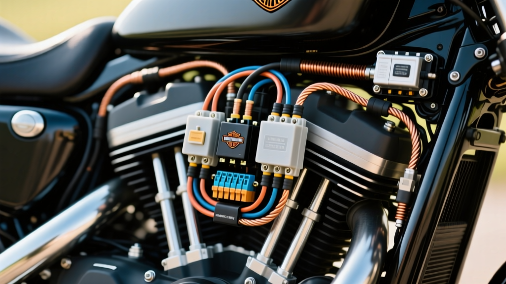
Decoding the OEM Harness for Aftermarket Upgrades
When undertaking an upgrade or modification project on a Milwaukee-made V-Twin, referencing an accurate Harley Davidson Sportster wiring diagram is not just a recommendation—it is a critical requirement for preventing catastrophic electrical failures. The Sportster platform (particularly the 2004-2013 XL883 and XL1200 models) utilizes a shunt-style voltage regulator and a 3-phase stator that operates near its maximum thermal limit with factory accessories. Adding high-draw components like LED auxiliary light bars, heated grips, or digital dash clusters without understanding the OEM routing and load limits will inevitably lead to a fried stator, a melted ignition switch harness, or an ECM failure due to voltage spikes.
This guide provides a comprehensive, expert-level breakdown of how to read the factory harness, identify safe tap points, and execute a high-amperage relay upgrade project without compromising the integrity of your motorcycle's charging system.
Understanding the Sportster Charging System Limits
Before splicing into any circuit, you must understand the amperage budget of the XL platform. The stock 32-amp stator produces roughly 22 to 24 amps of usable DC current at cruising RPM (2,500-3,000 RPM) after the voltage regulator rectifies and steps down the AC voltage. Unlike modern cars with 100+ amp alternators, the Sportster's electrical headroom is razor-thin.
| Component | Draw (Amps) | Notes |
|---|---|---|
| Ignition / ECM / Fuel Pump | 5.0A | Constant draw while key is ON |
| Headlight (H4 Halogen) | 5.0A (Low) / 9.0A (High) | Major load variable |
| Taillight / Brake Light | 2.0A / 4.5A | LED upgrades save ~3A here |
| Dash / Indicators / Speedo | 1.5A | Includes turn signal modules |
| Total Base Load | ~18.5A - 20.0A | Leaves only 2A - 4A headroom |
If you wire a 60W auxiliary light kit (drawing 5A) directly to the OEM headlight or ignition circuit, you will exceed the stator's output. The voltage regulator will remain in a constant 'shunt' state to bleed off excess heat, eventually melting the internal diodes. The correct modification protocol requires using the Harley Davidson Sportster wiring diagram to locate a low-amperage trigger wire, which then activates a dedicated relay block powered directly by the battery.
Identifying Safe Tap Points via the DLC Pinout
The most common mistake amateur builders make is tapping into the ignition switch harness behind the headlight bucket. The Sportster ignition switch is notoriously fragile, and the internal contacts are not rated for additional amperage. Overloading the switch leads to internal arcing, melting the 4-pin Molex connector, and leaving you stranded.
Instead, the factory provides a dedicated Diagnostic Link Connector (DLC) under the seat, which includes a switched 12V accessory circuit protected by a 15A fuse in the main fuse block. This is the ideal trigger point for aftermarket relay blocks.
| Pin | Wire Color | Function | Modification Use |
|---|---|---|---|
| 1 | Orange/White | Switched 12V (IGN) | Relay Trigger (Pin 85) |
| 2 | Green/White | Serial Data (CAN/J1850) | Do Not Tap |
| 3 | Pink | Tach Signal (Pre-CAN) | Aftermarket Tach Trigger |
| 4 | Black | Chassis Ground | Relay Ground (Pin 86) |
To tap into Pin 1 (Orange/White) without cutting the OEM wire, use a Metri-Pack 280 series female terminal with a pigtail lead. Insert the terminal into the unused cavity of a mating DLC connector, or use a high-quality T-tap if a mating connector is unavailable, though T-taps are discouraged for long-term reliability in high-vibration environments.
Project Execution: Installing a Fused Relay Block
For this modification, we are installing a 6-circuit fused relay block to power auxiliary LED fog lights, heated grips, and a USB charging port. This isolates the high-current draw from the OEM harness.
Step 1: Main Power Feed Routing
Run a 10 AWG primary wire (Red) from the positive terminal of the starter solenoid (not the battery post, to utilize the main 50A Maxi-fuse protection). Route the wire along the left side of the frame, avoiding the exhaust headers and steering neck. Secure the wire every 8 inches using UV-resistant zip ties with integrated mounting holes. Install an inline 30A ANL fuse within 6 inches of the solenoid connection.
Step 2: Grounding the Relay Block
Run a 10 AWG Black wire from the relay block's main ground bus to the battery negative terminal. Do not rely on frame grounding for the main relay block; the Sportster's powder-coated frame and engine isolation mounts can introduce resistance, leading to voltage drops and erratic relay operation.
Step 3: Wiring the Trigger Circuit
Using 14 AWG wire, connect the Orange/White DLC tap to the relay block's trigger input. This ensures that the relays only energize when the ignition is switched to the 'ON' position, preventing parasitic battery drain when the motorcycle is parked.
Wire Gauge and Connector Specifications
Adhering to SAE J1128 standards for low-tension primary cable is vital. Standard PVC-insulated wire becomes brittle and cracks when exposed to the ambient heat radiating from the Sportster's rear cylinder head. Always specify Cross-Linked Polyethylene (XLPE) or TXL/GXL wire, which is rated for continuous operation at 125°C (257°F).
| Circuit Type | AWG Size | Max Amperage | Terminal Type |
|---|---|---|---|
| Main Relay Feed | 10 AWG (TXL) | 30A | Ring Terminal (5/16') |
| Relay Trigger / Ground | 14 AWG (GXL) | 15A | Metri-Pack 280 / Spade |
| Aux Light Branches | 14 AWG (GXL) | 10A per circuit | Aptiv Metri-Pack 280 |
| USB Charger Branch | 16 AWG (GXL) | 5A | Deutsch DT (2-Pin) |
For all connections exposed to the elements, use adhesive-lined dual-wall heat shrink tubing. The inner meltable adhesive layer seals the crimp barrel against moisture ingress, preventing the green copper oxide corrosion that plagues poorly executed custom harnesses.
Voltage Regulator Grounding & ECM Protection
A critical, often overlooked aspect of the Sportster electrical system is the voltage regulator (VR) ground path. The VR does not have a dedicated ground wire; it grounds through its two mounting bolts to the engine crankcase. If you remove the VR for painting or frame modifications and fail to clean the mating surfaces, the VR will lose its ground reference. This causes the regulator to fail to shunt excess AC voltage, sending 16V+ spikes through the DC system that will instantly destroy the ECM and the speedometer.
Expert Tip: When reinstalling the VR, use a wire brush to remove all paint and corrosion from the frame mounting tabs. Apply a thin layer of dielectric grease over the bare metal after torquing the bolts to 120-180 in-lbs to prevent future oxidation, ensuring a flawless ground path.
Post-Installation Voltage Drop Testing
Once the modification is complete, do not simply turn on the accessories and assume the circuit is sound. Perform a voltage drop test across the main power feed and the ground circuits while the accessories are under load.
- Start the motorcycle and allow it to reach operating temperature.
- Turn on all auxiliary lights and heated grips.
- Set your digital multimeter to DC Volts.
- Place the red probe on the starter solenoid positive post and the black probe on the relay block's main power input terminal. A reading above 0.2V indicates excessive resistance (likely a poor crimp or undersized wire).
- Repeat the test on the ground side: Red probe on the relay block ground bus, black probe on the battery negative post. Again, the drop must not exceed 0.2V.
By strictly following the Harley Davidson Sportster wiring diagram and utilizing automotive-grade materials, your custom electrical upgrades will be reliable, safe, and capable of handling the harsh vibration and thermal cycles of the XL platform. For further reading on OEM schematics and diagnostic procedures, consult the Harley-Davidson Sportster Owner's Manual specific to your model year.