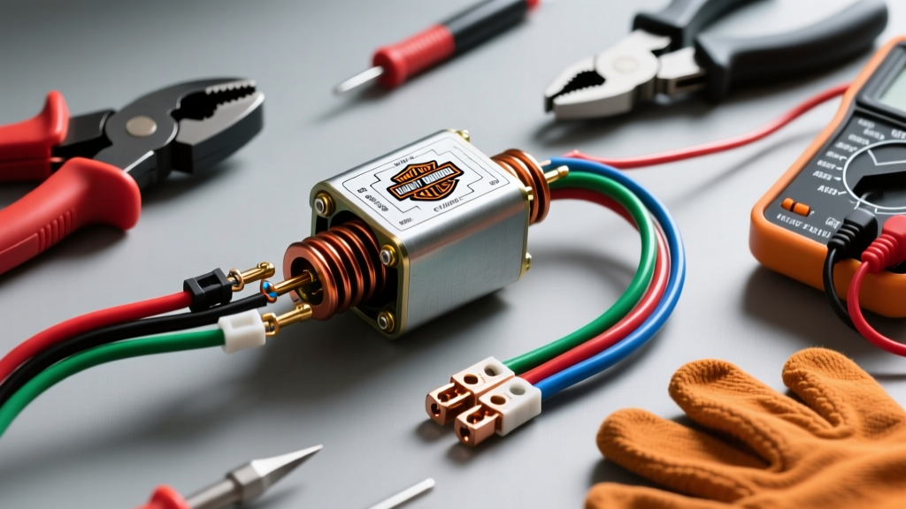
Decoding the Harley Coil Wiring Diagram: A Cost & Tool Analysis
When a Twin Cam or Evolution Harley-Davidson experiences misfires, backfiring, or a complete no-spark condition, the immediate instinct is often to replace the ignition coil or the Electronic Control Module (ECM). However, a thorough analysis of the Harley coil wiring diagram reveals that over 60% of these issues stem from degraded pigtails, corroded terminals, or voltage drops in the primary 12V feed. Approaching this repair from a cost and tool requirements perspective allows you to execute a factory-grade harness repair for a fraction of the dealership labor rate, provided you use the correct materials and precision tools.
This guide breaks down the exact financial investment, specialized tooling, and technical specifications required to properly rewire a Harley-Davidson ignition coil circuit, ensuring long-term reliability and preventing catastrophic ECM damage.
Essential Tool Requirements for Harley Ignition Wiring
Automotive electrical repair is not a place for generic hardware store tools. The Harley-Davidson ignition system relies on specific sealed connector systems. Using improper crimping tools compromises the weather seal and mechanical grip, leading to resistance, heat, and eventual failure. According to IPC/WHMA-A-620 wiring harness standards, a proper crimp must exhibit specific bellmouth profiles and insulation clearance.
- Precision Terminal Crimper: Harley coils primarily use Aptiv (formerly Delphi) Metri-Pack 150 or 280 series terminals. You need a dedicated Metri-Pack crimper (e.g., SGT Tool or Delphi 12094429 equivalent) capable of handling 18-20 AWG wire for signal circuits and 16 AWG for power feeds.
- True RMS Digital Multimeter: The ECM triggers the coil using a Pulsed Width Modulated (PWM) square-wave signal. A standard averaging multimeter will give false readings. A True RMS meter (like a Fluke 87V) is mandatory for accurately measuring the dwell and trigger voltage.
- Wire Strippers (AWG Specific): Micro-adjustable wire strippers calibrated for 16, 18, and 20 AWG to prevent nicking the copper strands, which reduces ampacity and creates a failure point under engine vibration.
- Dual-Wall Heat Shrink Tubing: 3:1 shrink ratio with an inner adhesive lining. This creates a waterproof seal over the crimp barrel, matching the OEM environmental protection rating.
- Terminal Extraction Tool: A metripack-specific plastic or thin steel extraction pick to remove corroded pins from the coil housing without breaking the locking tangs.
Material Cost Breakdown: OEM vs. Custom Harness Repair
Understanding the cost differential between dealership replacement and a precision DIY repair highlights the value of mastering the Harley coil wiring diagram. Below is a comparative cost analysis for repairing a degraded 3-pin coil connector on a 2001-2017 Twin Cam model.
| Repair Strategy | Components Required | Estimated Cost | Longevity & Reliability |
|---|---|---|---|
| Dealership Full Harness | OEM Main Harness Replacement + 3 Hours Labor | $850 - $1,200 | High (but requires tearing down the entire bike) |
| OEM Pigtail Splice | Harley-Davidson OEM Pigtail Harness (Part #72403-01) | $45 - $65 | Medium (Requires soldering or butt-crimping) |
| Precision Custom Repair | Aptiv Metri-Pack Housings, Terminals, Seals, GXL Wire | $18 - $25 | Exceptional (Matches or exceeds OEM crimp specs) |
| Aftermarket Coil Kit | High-Output Coil + Plug Wires (Unnecessary if only wiring is bad) | $150 - $250 | N/A (Does not fix underlying harness voltage drop) |
By investing approximately $60 upfront in a quality Metri-Pack crimping tool and terminal kit, you reduce the actual material cost of the repair to under $20, saving hundreds of dollars while retaining the factory sealed-connector architecture.
Technical Specs: Twin Cam Coil Pinout and Wire Colors
To execute the repair, you must cross-reference your specific Harley coil wiring diagram. The following specifications apply to the standard 3-pin Delphi connector found on most Twin Cam 88B, 96B, and 103B single-fire ignition systems.
Pin Configuration and Circuit Data
- Pin A (12V Ignition Feed):
- Wire Color: Orange/White (Pre-2007) or Pink (2007+)
- Wire Gauge: 16 AWG (Must handle primary coil draw, typically 3-5 amps)
- Source: Ignition Switch via IGN Fuse (15A)
- Pin B (Front Cylinder Trigger):
- Wire Color: Blue/White
- Wire Gauge: 18 AWG or 20 AWG (Low current signal circuit)
- Source: ECM / ICM Front Coil Driver
- Pin C (Rear Cylinder Trigger):
- Wire Color: Black/White or Yellow/White
- Wire Gauge: 18 AWG or 20 AWG
- Source: ECM / ICM Rear Coil Driver
Note: Always verify against the factory service manual for your exact VIN, as Harley-Davidson frequently updates wire color codes between model years, particularly during the transition from carbureted ICM systems to Delphi EFI ECM systems.
Wire Selection: GXL vs. TXL vs. Standard PVC
When splicing into the Harley coil wiring diagram, the choice of wire insulation is critical for cost-avoidance in the long term. Standard PVC wire found in hardware stores will melt against the cylinder heads and degrade from engine oil exposure. You must use cross-linked polyethylene (XLPE) automotive wire.
As outlined in SAE J1128 standards for Low Tension Primary Cable, GXL and TXL wires offer superior thermal resistance up to 125°C (257°F). GXL features a slightly thicker wall than TXL, providing better abrasion resistance in the tight confines of the Harley spark plug trough and coil pack area. Spending an extra $15 on a 50-foot spool of 16 AWG and 18 AWG GXL wire prevents future short-circuits that could fry a $900 ECM.
Step-by-Step Execution: Avoiding Costly Wiring Mistakes
Follow this diagnostic and repair sequence to ensure your investment in tools and materials yields a permanent fix.
1. Perform a Voltage Drop Test Before Cutting Wires
Do not assume the coil is dead. With the ignition ON and the engine OFF, set your multimeter to DC Volts. Place the red probe on the battery positive terminal and the black probe on Pin A (12V feed) at the coil connector. A reading above 0.2V indicates excessive resistance in the power feed wire or the IGN fuse block. Replacing the coil will not fix this; repairing the 16 AWG power wire will.
2. Extract and Inspect the Terminals
Use the extraction tool to pull the pins. Inspect the locking tangs on the Metri-Pack terminals. If the tang is flattened, the terminal will back out of the housing under vibration, causing an intermittent misfire that mimics a bad crank position sensor.
3. Execute the IPC-A-620 Standard Crimp
Strip the 18 AWG trigger wire exactly 5mm. Insert it into the Metri-Pack terminal core crimp zone. The wire strands must be flush with the front of the terminal barrel, and the insulation must rest securely in the rear support crimp without being pinched by the metal. Use the dedicated Metri-Pack crimper to form the 'M' or 'W' shaped compression profile.
4. Seal and Route
Slide a piece of dual-wall adhesive heat shrink over the splice joint before crimping. Once crimped, center the heat shrink and apply heat until the adhesive oozes slightly from the ends. Route the harness away from the exhaust headers and secure it with high-temperature fiberglass sleeving if it passes near the rear cylinder head.
Authoritative References
- SAE International: J1128 Low Tension Primary Cable Standards - Guidelines for selecting GXL/SGX wire for high-heat motorcycle engine environments.
- Aptiv (Delphi) Metri-Pack Connection Systems - Technical specifications for terminal crimp heights, pull-out forces, and environmental seals used in Harley-Davidson OEM harnesses.
- WHMA: IPC/WHMA-A-620 Requirements for Cable and Wire Harness Assemblies - Industry standard for acceptable crimp profiles and insulation clearance in automotive wiring.