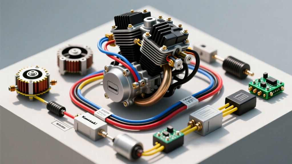
Adapting the Kawasaki FR691V for Custom Motorcycle and Trike Builds
The Kawasaki FR691V 726cc V-Twin has become a legendary staple in the custom motorcycle, off-road trike, and sand rail community. Its compact dimensions, massive low-end torque, and air-cooled reliability make it an ideal powerplant for custom three-wheeled builds and off-road buggies. However, adapting an industrial engine harness to a motorcycle chassis requires a deep understanding of the Kawasaki FR691V wiring diagram. Industrial engines do not use standard automotive 12V logic for ignition, and misinterpreting the stator or kill circuits is the leading cause of electrical fires and no-spark conditions in custom V-twin swaps.
This practical installation guide will walk you through routing the stator, configuring the ground-to-kill ignition circuit, and integrating the starter solenoid into a custom motorcycle harness using proper AWG sizing and sealed connectors.
Essential Wire Gauge and Connector Specifications
Before cutting or splicing any wires, you must select the correct marine-grade or automotive-grade wiring. The FR691V stator outputs significant AC current, and voltage drop on the DC side will fry the voltage regulator. According to SAE J1128 standards for low-tension primary cables, you must use stranded copper wire with high-temperature insulation (XLPE or PVC rated for 125°C).
| Circuit Type | AWG Size | Connector Type | Insulation / Sealing |
|---|---|---|---|
| Stator to Regulator (AC) | 14 AWG | Deutsch DT 2-Pin or Sumitomo HM | Adhesive-lined heat shrink |
| Regulator to Battery (DC+) | 10 AWG | Ring Terminal (5/16 inch) | Marine-grade heat shrink |
| Regulator Ground (DC-) | 10 AWG | Ring Terminal to Engine Block | Star washer, dielectric grease |
| Ignition Kill Switch | 16 AWG | Spade / Weather-Pack | Standard heat shrink |
| Starter Motor Feed | 6 AWG | Heavy Duty Ring Terminal | Self-fusing silicone tape |
Step-by-Step Kawasaki FR691V Wiring Installation
Step 1: Stator to Voltage Regulator/Rectifier Routing
The FR691V utilizes a single-phase stator that outputs AC voltage. This must be converted to 12V DC to charge your custom trike or motorcycle battery. The stator harness typically exits the engine case with two Yellow wires. These carry raw AC power and should never be grounded to the chassis.
- Route the Stator Wires: Run the two Yellow 14 AWG wires from the stator up to the voltage regulator/rectifier mounting location. Keep these wires away from the exhaust headers and moving throttle linkages.
- Connect to the Regulator: Plug the two Yellow wires into the corresponding Yellow pins on the regulator. Because this is an AC single-phase system, polarity on these two specific pins does not matter.
- Wire the DC Output: The regulator will have a Red wire (DC+ Output) and a Black wire (Ground). Connect the Red 10 AWG wire directly to the positive terminal of your battery or the main motorcycle starter solenoid post. Never route the regulator Red wire through the ignition switch; it must have a direct, unswitched path to the battery to handle peak amperage without melting the ignition switch contacts.
- Establish a Clean Ground: Connect the Black 10 AWG ground wire directly to a clean, unpainted surface on the engine block. Use a star washer to bite through any powder coating or corrosion. A poor ground will cause the regulator to overheat and fail within hours.
Step 2: Ignition Coil and Kill Switch Circuit
This is where most industrial-to-motorcycle engine swaps fail. The Kawasaki FR691V uses a transistorized magneto ignition system. Unlike automotive systems that send 12V+ to the coil to create a spark, the FR691V coils are constantly energized by the magneto flywheel. To stop the engine, the system uses a ground-to-kill logic.
- Identify the Kill Wires: Locate the White wires coming from the ignition coils. These are the primary kill circuit wires.
- Isolate from the Chassis: Ensure the White wires are completely insulated and isolated from the engine block and motorcycle frame. If these wires touch the frame, the engine will not spark.
- Wire the Kill Switch: Run a 16 AWG wire from your custom motorcycle handlebar kill switch (set to the 'Ground' or 'Magneto' position) to the White kill wires. When you flip the switch to 'Off', it bridges the White wire to the chassis ground, shorting the primary coil circuit and killing the spark instantly.
- Optional 12V Relay Integration: If your custom trike uses a modern digital dash that requires a 12V+ signal to know the engine is running, use a standard 12V automotive relay. Wire the relay coil between the ignition coil primary wire and ground to trigger the dash signal without interfering with the magneto kill circuit.
Step 3: Starter Solenoid and Battery Integration
The FR691V starter motor draws upwards of 80-120 amps under load. You must use a heavy-duty external solenoid (commonly found in motorcycle or ATV winch setups) to handle the current.
- Main Power Feed: Run a 6 AWG red cable from the battery positive terminal to the large input stud on the starter solenoid.
- Starter Feed: Run a second 6 AWG cable from the solenoid output stud directly to the FR691V starter motor terminal.
- Trigger Circuit: Use a 14 AWG wire to connect the solenoid trigger spade to your handlebar start button. The start button should receive 12V+ from a switched ignition source. When pressed, it sends 12V+ to the solenoid coil, bridging the heavy contacts and engaging the starter.
FR691V Pinout and Wire Color Reference Chart
Use this reference chart when verifying your engine harness against aftermarket motorcycle wiring harnesses. Always verify with a multimeter, as previous owners of used engines may have spliced in non-standard colors.
| Wire Color | Function | Destination / Connection | Voltage / Signal Type |
|---|---|---|---|
| Yellow (x2) | Stator AC Output | Voltage Regulator (AC Pins) | 28V - 60V AC (RPM dependent) |
| Red | Regulator DC Output | Battery Positive (+) | 13.8V - 14.4V DC |
| Black | Regulator Ground | Engine Block / Chassis | Ground (0V) |
| White | Ignition Kill | Handlebar Kill Switch | Ground to Kill (Magneto Short) |
| Red (Heavy) | Starter Motor Power | Solenoid Output Stud | 12V DC (Cranking only) |
Real-World Troubleshooting: Common V-Twin Electrical Failures
When building a custom motorcycle with an FR691V, electrical gremlins are common. Use this decision tree and multimeter testing guide to diagnose issues based on standard Kawasaki service documentation principles.
Symptom: Battery is Not Charging (Reads 12.2V at 3000 RPM)
- Test 1: Stator AC Output. Unplug the regulator. Set your multimeter to AC Volts. Probe the two Yellow stator wires while the engine is running at 3000 RPM. You should read between 28V and 50V AC. If you read 0V or very low voltage, the stator is burnt out or the flywheel magnets have separated.
- Test 2: Regulator Ground. If AC output is good, check the voltage drop on the Black ground wire. Place one probe on the battery negative and one on the regulator casing. If you read more than 0.2V DC, your ground connection is corroded. Clean the mounting point and retest.
- Test 3: Parasitic Draw. If the battery dies overnight, the regulator diodes may be shorted, allowing battery current to flow back into the stator. Disconnect the Red regulator wire when the bike is parked to verify.
Symptom: Engine Has No Spark (Cranking but Won't Start)
- Check 1: Kill Switch Logic. Remember that the FR691V uses a ground-to-kill system. If your custom handlebar switch is designed for an automotive 12V+ coil, it will not work. Ensure your kill switch is physically grounding the White wire to the frame when in the 'Run' position (if wired inversely) or that the White wire is completely isolated from ground during cranking.
- Check 2: Coil Resistance. Disconnect the spark plug wires and the primary coil wires. Use an ohmmeter to measure primary resistance (should be 0.5 to 2.0 ohms) and secondary resistance (should be 10,000 to 15,000 ohms). Out-of-spec readings indicate a failed ignition coil.
- Check 3: Air Gap. Verify the clearance between the magneto flywheel and the ignition coil pickups. It must be exactly 0.2mm to 0.5mm. A dropped engine or improper reassembly can widen this gap, resulting in a weak or non-existent spark.
Final Assembly and Sealing Best Practices
Because custom trikes and off-road motorcycles are exposed to extreme vibration, water, and debris, standard electrical tape is strictly prohibited. Every connection on your FR691V swap must be soldered or crimped using a ratcheting crimper, then sealed with adhesive-lined dual-wall heat shrink tubing. For any connectors exposed to the elements, such as the stator-to-regulator plug, apply a dab of dielectric grease inside the Deutsch or Weather-Pack connectors before mating them to prevent moisture ingress and galvanic corrosion.
By strictly following this Kawasaki FR691V wiring diagram guide and respecting the unique ground-to-kill and high-amperage AC requirements of this V-Twin, your custom motorcycle build will feature a reliable, road-ready electrical system capable of handling modern LED lighting, digital gauges, and extended off-road abuse.