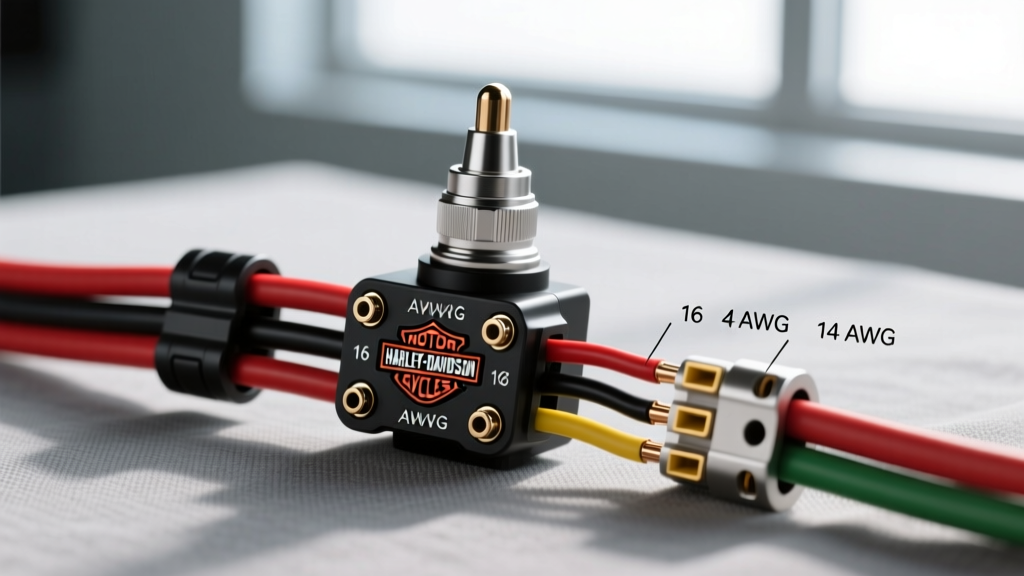
OEM Harley Accessory Plug Wiring Diagram Overview
Integrating auxiliary lighting, heated gear, GPS navigation, or custom audio into late-model Harley-Davidson touring and softail platforms requires a thorough understanding of the OEM accessory harness. Unlike older carbureted or early EFI models that relied on simple analog relays and direct battery feeds, modern Milwaukee-Eight and Twin Cam platforms utilize a multiplexed electrical architecture. The Body Control Module (BCM) actively monitors current draw on accessory circuits, and the CAN bus network dictates data flow.
This advanced technical deep dive provides a comprehensive Harley accessory plug wiring diagram, detailing the proprietary 6-pin AMP/Molex-style connector typically located under the left side panel or seat on FLHR, FLHT, and FLHX models. We will cover exact pin configurations, wire gauge (AWG) requirements, BCM load limitations, and SAE-compliant termination strategies to ensure your custom electrical work is reliable, safe, and free of diagnostic trouble codes (DTCs).
6-Pin Accessory Connector Pinout & Specifications
The OEM 6-pin accessory plug (often referenced in service manuals under the Tour-Pak or auxiliary lighting harness sections) serves as the primary interface for dealer-installed and aftermarket accessories. Below is the definitive pinout table for 2014+ Project RUSHMORE and newer touring models. Note that wire colors may feature a secondary tracer stripe.
| Cavity (Pin) | Wire Color | AWG Size | Function / Circuit | Max Continuous Load |
|---|---|---|---|---|
| 1 | Black (BK) | 14 AWG | Chassis Ground (GND) | 20A |
| 2 | Gray (GY) | 16 AWG | Switched 12V (IGN/ACC) | 5A (BCM Protected) |
| 3 | Green/White (GN/WT) | 20 AWG | CAN High (J1939) | Signal Only |
| 4 | Green/Black (GN/BK) | 20 AWG | CAN Low (J1939) | Signal Only |
| 5 | Red/White (R/WT) | 14 AWG | Unswitched Battery Direct (B+) | 20A (Fused at PDB) |
| 6 | Yellow/Gray (YE/GY) | 18 AWG | Accessory Enable / Data | 2A |
Technical Note: Pin 2 (Gray) is the most commonly tapped circuit for auxiliary light switches. However, because it is routed through the BCM, exceeding the 5A threshold will cause the BCM to shut down the circuit and log a B-code (e.g., B1151 - Accessory Circuit Overcurrent). Always use Pin 2 strictly as a low-current trigger signal for an external relay.
Body Control Module (BCM) Load Limits & Relay Integration
When designing high-draw circuits like off-road LED bars or heated clothing controllers, you must bypass the BCM's internal solid-state switches. The correct methodology is to use Pin 2 as a trigger for a BOSCH-style 30A or 40A automotive relay, while pulling the heavy current directly from Pin 5 (Battery Direct) or running a dedicated 10 AWG feed directly from the starter B+ post.
Relay Wiring Topology for High-Draw Accessories
- Relay Pin 85 (Coil Ground): Connect to Pin 1 (Black, 14 AWG) of the accessory plug.
- Relay Pin 86 (Coil Trigger): Connect to Pin 2 (Gray, 16 AWG). The BCM will supply 12V here when the ignition is ON.
- Relay Pin 30 (Common / Power In): Connect to Pin 5 (Red/White, 14 AWG) for up to 15A continuous, or run a dedicated 12 AWG wire with an inline MAXI fuse directly to the battery positive terminal for loads exceeding 15A.
- Relay Pin 87 (Normally Open / Power Out): Route to your auxiliary accessory (e.g., LED light bar positive terminal).
By isolating the high-amperage load from the BCM, you prevent thermal shutdowns and ensure the motorcycle's primary data bus remains stable.
CAN Bus (J1939) Topology & Splicing Rules
Pins 3 and 4 on the Harley accessory plug provide access to the high-speed CAN bus network, which operates at 500 kbps. This is essential for integrating smart dashes, GPS telemetry units, or custom ECM tuners that need to read RPM, vehicle speed, and engine temperature.
According to the SAE J1939 CAN Bus Topology standards, the CAN bus is a daisy-chained linear network terminated at both ends by 120-ohm resistors, resulting in a parallel impedance of 60 ohms across the network. When splicing into Pins 3 (CAN High) and 4 (CAN Low):
- Never create a star network: Stubs (the wire length from the main CAN trunk to your device) must not exceed 0.3 meters (12 inches). Longer stubs cause signal reflection and phase shifting, leading to U-codes (e.g., U0001 - High Speed CAN Communication Bus Fault).
- Maintain the twist: CAN High and CAN Low wires are twisted together to reject electromagnetic interference (EMI) from the stator and ignition coils. Maintain at least 2 twists per inch when extending the harness.
- Use proper solder sleeves: Do not use T-taps or scotch locks on CAN lines. Use heat-shrink solder sleeves or high-quality crimp splices to maintain the exact impedance of the twisted pair.
Wire Selection: SAE J1128 Standards
When extending the OEM harness, never use generic PVC wire from a hardware store. The engine bay and under-seat areas of a Harley-Davidson routinely exceed 100°C (212°F), and standard PVC insulation will melt, short against the frame, and cause a catastrophic fire.
Always specify SAE J1128 Standard compliant wire, specifically TXL (Thin-wall) or GXL (General-purpose thin-wall) cross-linked polyethylene (XLPE). TXL wire features a smaller outer diameter than GXL, allowing you to route additional circuits through the OEM frame conduit without pinching. Furthermore, XLPE insulation is rated for 125°C continuous operation and is highly resistant to the oils, fuels, and solvents common in garage environments.
Advanced Troubleshooting: Voltage Drop & Parasitic Draws
Even with a perfect wiring diagram, poor terminations will ruin an electrical system. Use a high-quality digital multimeter (DMM) to verify circuit health post-installation.
Voltage Drop Testing
Instead of measuring resistance (which is ineffective on long, live circuits), perform a voltage drop test under load. Set your DMM to DC Volts. Place the red probe on the battery positive terminal and the black probe on the accessory's positive input terminal while the circuit is active. A healthy 14 AWG circuit should show a voltage drop of less than 0.2V. If the drop exceeds 0.5V, you have excessive resistance, likely caused by a loose crimp or undersized wire.
Parasitic Draw Verification
Harley-Davidson motorcycles have multiple modules that take up to 20 minutes to enter 'sleep' mode after the ignition is turned off. To test for parasitic draws:
- Disconnect the negative battery terminal.
- Connect the DMM in series (set to 10A DC) between the negative battery post and the disconnected cable.
- Turn the ignition OFF, remove the key, and wait 30 minutes for the BCM and ECM to fully power down.
- Switch the DMM to the mA scale. The acceptable parasitic draw for a modern Harley with an OEM alarm system is typically between 2mA and 5mA. If you read >10mA, an aftermarket accessory wired to Pin 5 (Unswitched B+) is failing to sleep or has a shorted internal component.
Termination and Crimp Tooling Requirements
The OEM 6-pin connector utilizes specific stamped-and-formed terminals. Attempting to crimp these with standard pliers will result in cold joints, leading to arcing and melted connector housings. For TE Connectivity / AMP style connectors, you must use a ratcheting crimper calibrated for the specific AWG and terminal series. The TE Connectivity Automotive Crimp Standards dictate that a proper crimp will exhibit a bell-mouth shape at the insulation and conductor crimps, ensuring maximum tensile strength and optimal electrical conductivity. Always perform a pull-test on your crimps before inserting them into the connector housing.