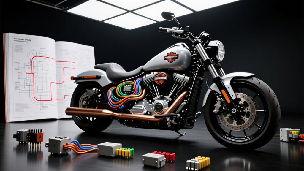
Introduction: Navigating the Electra Glide Electrical Labyrinth
Touring motorcycles like the Harley-Davidson Electra Glide (FLHT, FLHTCU, FLHX) feature some of the most complex electrical harnesses in the motorcycle industry. With the addition of fairing-mounted audio systems, heated grips, cruise control, and extensive lighting arrays, tracing a parasitic draw or a dead circuit requires more than just a basic multimeter. While finding a reliable electra glide free harley davidson wiring diagram online is a great starting point, the true challenge lies in interpreting the schematic and applying a systematic troubleshooting flow to isolate the fault. This guide provides a professional, step-by-step diagnostic workflow tailored specifically for Electra Glide touring models, focusing on real-world failure points, connector pinouts, and precise multimeter testing procedures.
Step 1: Decode the Schematic and Wire Color Codes
Factory Harley-Davidson wiring diagrams utilize a specific alphanumeric grid system (e.g., Grid 4A, 5B) to help you locate components on the page. More importantly, they rely on a standardized color-coding abbreviation system. Before you begin probing wires in the fairing or under the seat, you must understand how the diagram denotes primary colors and tracer stripes. According to Nightrider HD Wiring Tech, misinterpreting a tracer color is the leading cause of misdiagnosis in custom and repair jobs.
| Abbreviation | Color | Common Electra Glide Application | Typical AWG |
|---|---|---|---|
| BK | Black | Main Ground / Negative | 18 AWG - 8 AWG |
| R | Red | Unswitched Battery Positive | 14 AWG - 6 AWG |
| O | Orange | Switched Ignition / Accessory Power | 18 AWG - 14 AWG |
| W | White | Lighting / High Beam / Turn Signal | 18 AWG |
| V | Violet | Data Bus / Tachometer / Speedometer | 20 AWG - 18 AWG |
| Y | Yellow | Stator 3-Phase AC Output | 12 AWG |
| G/BN | Green w/ Brown Tracer | Left Turn Signal / Audio Mute | 18 AWG |
Step 2: Isolate the Circuit (Power vs. Ground Faults)
When an Electra Glide component fails (e.g., the right saddlebag running light is dead), do not immediately start tearing apart the harness. Use your schematic to determine if the fault is on the power side or the ground side. Touring models are notorious for ground faults due to vibration and exposure to road debris.
The Voltage Drop Test
Never rely solely on continuity testing for grounds; a single strand of 18 AWG wire can show continuity on a multimeter but will fail under the actual load of a bulb. Instead, perform a voltage drop test with the circuit powered on.
- Set your multimeter to DC Volts.
- Place the red probe on the known good battery positive terminal.
- Place the black probe on the component's power input pin. A reading above 0.5V indicates excessive resistance (corrosion or a broken strand) in the power wire.
- Next, place the red probe on the component's ground output pin, and the black probe on the battery negative terminal. A reading above 0.1V indicates a poor ground connection.
Expert Insight: On FLHTCU Ultra Classics, the main engine ground strap (typically 8 AWG or 6 AWG) connects the battery negative to the crankcase. If this strap corrodes, the engine will attempt to ground through the throttle cables or the speedometer braided wire, causing erratic gauge behavior and melted speedometer internals.
Step 3: Trace the Harness (Electra Glide Specific Pain Points)
The most common area for wiring faults on the Electra Glide is the transition point between the frame harness and the fairing/lower fairing harness. The steering neck area subjects the wiring to constant articulation, leading to insulation chafing and copper fatigue.
Troubleshooting Decision Tree: Fairing Cap to Lower Fairing Connector
If you are experiencing intermittent passing lamp operation, radio static, or gauge cluster dropouts, follow this diagnostic flow for the 18-pin or 24-pin Metri-Pack/Delphi connector located inside the fairing dash:
- Symptom: Passing lamps do not work, but high beams function normally.
- Check: Left and right handlebar switch housings for moisture ingress.
- Trace: Follow the Violet/White (Left) and Brown/White (Right) wires from the switch down to the fairing cap connector.
- Verify: Check for pushed-out pins inside the Metri-Pack connector. The locking tangs on these 18-pin connectors frequently fail, allowing the pin to back out when the harness is pulled taut during steering.
- Symptom: Speedometer drops to zero intermittently over bumps.
- Check: The Vehicle Speed Sensor (VSS) located on the transmission housing.
- Trace: The White/Green and Black/White twisted pair running up to the dash.
- Verify: Inspect the harness where it zip-ties to the frame backbone under the gas tank. The sharp edge of the tank bracket often wears through the loom, shorting the VSS signal wire (White/Green) to ground.
Step 4: Component & Pinout Verification (Stator and Voltage Regulator)
Electra Glides draw significant amperage, especially when equipped with heated clothing, auxiliary driving lights, and high-wattage audio amplifiers. The charging system is under constant stress. When using your wiring diagram to diagnose a dead battery, you must verify the 5-pin Voltage Regulator (VR) connector, a known failure point on Twin Cam 88, 96, and 103 engines.
| Pin Number | Wire Color | Function | Diagnostic Specification |
|---|---|---|---|
| 1 | Yellow (Y) | Stator Phase 1 AC Input | ~20VAC per 1000 RPM (to Pin 2) |
| 2 | Yellow (Y) | Stator Phase 2 AC Input | ~40VAC per 1000 RPM (to Ground) |
| 3 | Red (R) | Battery Positive Output | 13.8V - 14.5V DC at 2000 RPM |
| 4 | Red (R) | Battery Positive Output | 13.8V - 14.5V DC at 2000 RPM |
| 5 | Black (BK) | Main Chassis Ground | < 0.1V Drop under 30A Load |
Testing Procedure: Disconnect the VR connector. Set your multimeter to AC Volts. Start the motorcycle and measure across Pins 1 and 2. You should see roughly 20VAC at 1000 RPM, scaling linearly to 60VAC+ at 3000 RPM. If you read 0VAC, your stator is open-circuit. If you read voltage but the battery isn't charging, check the 30A main fuse located near the starter solenoid, and inspect the Red output wires for heat-melted insulation near the VR body.
Step 5: Repair Standards and SAE Compliance
Once the fault is isolated using the diagram and your multimeter, the repair must meet stringent automotive and motorcycle standards. The engine compartment and primary drive areas of an Electra Glide easily exceed 250°F (121°C) during slow-moving parade traffic or hot summer touring.
According to the SAE J1128 Standard for Low Tension Primary Cable, you must use SGT (Standard Gauge Thermoplastic) or SGX (Cross-linked Polyethylene) wire for any repairs routed near the engine block, exhaust headers, or oil cooler lines. SGX wire features a much thinner, highly heat-resistant insulation that can withstand continuous temperatures up to 150°C (302°F), whereas standard PVC wire will melt and short out against the frame.
Proper Splicing and Sealing
- Strip and Crimp: Use an open-barrel crimp tool for Metri-Pack terminals. Never use solder-only splices in high-vibration motorcycle harnesses; solder wicks into the wire strands, creating a rigid point that will snap under harmonic vibration.
- Heat Shrink: Use dual-wall, adhesive-lined heat shrink tubing. When heated, the inner wall melts and seals the splice from moisture and road salt, preventing the green corrosion (copper oxide) that plagues older FLHT models.
- Dielectric Grease: Apply a liberal amount of silicone dielectric grease to all Deutsch DT and Metri-Pack connectors before reassembly. This displaces moisture and prevents the locking tangs from seizing, ensuring that the next time you need to consult your electra glide free harley davidson wiring diagram, the connectors will separate without breaking.
Conclusion
Mastering the electrical system of an Electra Glide requires patience, a high-quality digital multimeter, and a methodical approach to reading wiring diagrams. By understanding the factory color codes, utilizing voltage drop testing instead of basic continuity checks, and focusing on known mechanical stress points like the steering neck and VR connectors, you can diagnose and repair complex faults with confidence. Always adhere to SAE standards for wire selection and sealing to ensure your touring machine remains reliable for thousands of miles down the road.