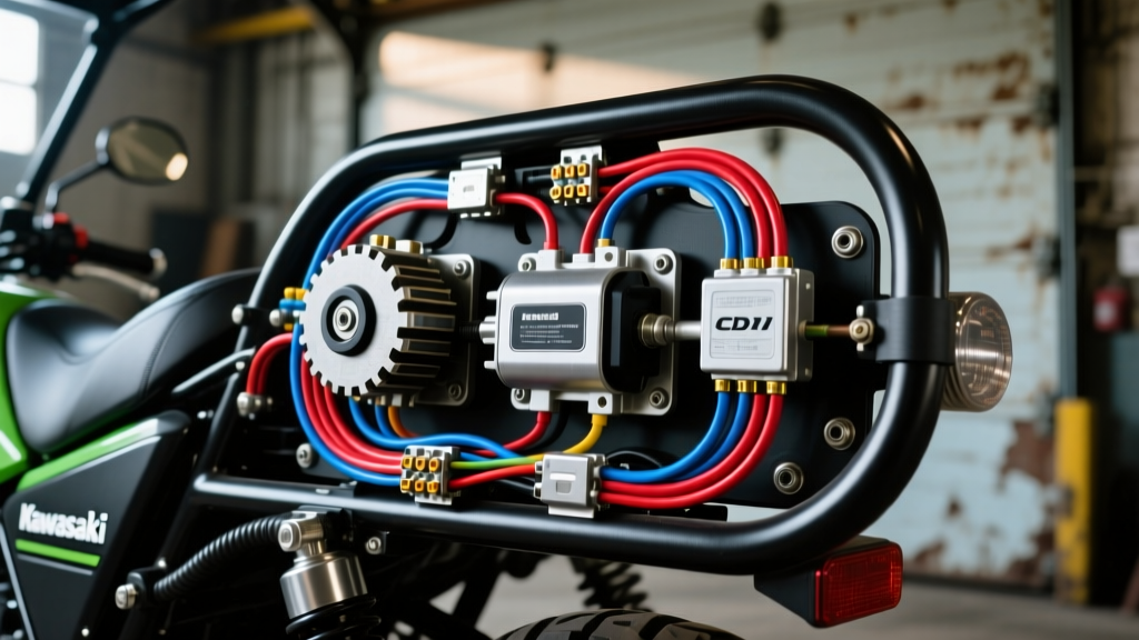
Navigating the Kawasaki Mule 2510 Wiring Diagram for Component Selection
The Kawasaki Mule 2510, powered by the robust 617cc V-twin engine, relies on a deceptively simple but highly stressed electrical system. When components fail or when owners upgrade for heavy-duty accessory use, the Kawasaki Mule 2510 wiring diagram becomes the essential blueprint for selecting replacement parts. Unlike modern fuel-injected side-by-sides, the Mule 2510 utilizes a traditional CDI (Capacitor Discharge Ignition) system, a 3-phase stator, and a shunt-style regulator/rectifier. Understanding the specific wire color codes, AWG (American Wire Gauge) requirements, and connector pinouts detailed in the factory diagram is critical when comparing OEM replacements against high-performance aftermarket alternatives. This guide breaks down the selection process for wiring harnesses, stators, and ignition components, ensuring your electrical upgrades match or exceed factory specifications.
OEM vs. Aftermarket Wiring Harness Comparison
When a harness melts due to a short circuit or degrades from UV and heat exposure, owners must choose between an OEM Kawasaki replacement, a direct-fit aftermarket harness, or a custom-built loom. The factory Kawasaki Mule 2510 wiring diagram specifies standard PVC-jacketed wires, which are prone to brittle failure near the exhaust headers. Upgrading to cross-linked polyethylene (XLPE) or Tefzel insulation drastically improves heat resistance. Below is a technical comparison of harness selection options based on material science and SAE J1128 low-tension primary cable standards.
| Harness Option | Wire Jacket Material | Primary AWG Specs | Connector Type | Best Use Case |
|---|---|---|---|---|
| OEM Kawasaki | PVC (Polyvinyl Chloride) | 16-18 AWG (10 AWG B+) | Sumitomo TS Series | Stock restoration, budget repairs |
| RM Stator Direct-Fit | XLPE (Cross-Linked) | 14-16 AWG (8 AWG B+) | Sumitomo TS / Deutsch DT | High-heat environments, longevity |
| Custom Painless Loom | Tefzel (TXL/GXL) | 12-14 AWG (6 AWG B+) | Weather-Pack / Metri-Pack | Heavy accessory loads, winches, lights |
When selecting an aftermarket harness, verify that the main power feed (typically Red) and main ground (Black/Green) are upgraded to at least 10 AWG. The factory diagram routes the main ground to the engine block; ensuring this connection uses a heavy-gauge wire with a star-washer termination is vital for completing the high-current starter circuit.
Stator and Regulator/Rectifier Selection Guide
The charging system is the most common failure point on the Mule 2510. The factory wiring diagram shows three Yellow wires (Y) routing from the stator to the regulator/rectifier (R/R). The OEM R/R is a shunt-type design, which works by intentionally shorting the stator phases to ground to bleed off excess voltage. This generates massive heat, often melting the 3-pin stator connector. When selecting a replacement, you must decide between replicating the OEM shunt design or upgrading to a series MOSFET regulator.
Stator Output Specifications
When consulting the Kawasaki Mule 2510 wiring diagram for stator selection, ensure the replacement matches the factory output. A healthy OEM-equivalent stator should produce a minimum of 20V AC at idle (1,200 RPM) and exceed 50V AC at 3,000 RPM between any two of the three Yellow phases. According to RM Stator Technical Documentation, selecting a stator with reinforced epoxy potting and 14 AWG output pigtails will prevent the internal winding shorts common in older units.
MOSFET Regulator Upgrade Pinout
If you select a series MOSFET regulator (such as the SH775) to replace the OEM shunt unit, the wiring diagram must be modified. The MOSFET unit does not bleed excess energy as heat; it simply stops drawing current when the battery is full. This requires bypassing the factory harness connectors and running dedicated heavy-gauge wires directly to the battery.
| MOSFET R/R Pin | Wire Color | AWG | Connection Destination |
|---|---|---|---|
| Phase A | Yellow | 14 AWG | Stator Phase A (Solder & Heat Shrink) |
| Phase B | Yellow | 14 AWG | Stator Phase B (Solder & Heat Shrink) |
| Phase C | Yellow | 14 AWG | Stator Phase C (Solder & Heat Shrink) |
| B+ (Output) | Red | 10 AWG | Battery Positive (via 50A Inline Fuse) |
| Ground | Black | 10 AWG | Battery Negative / Clean Chassis Ground |
CDI, Pulsar Coil, and Ignition Wiring Selection
The ignition system on the 617cc V-twin relies on a dual-output CDI and a magnetic pulsar coil (pickup). The Kawasaki Mule 2510 wiring diagram identifies the pulsar coil wires as White/Red and White/Black. When selecting a replacement CDI or pickup assembly, resistance matching is critical. The pulsar coil should read between 360 and 540 ohms at room temperature. If you are building a custom harness for a custom ignition setup, you must use shielded 18 AWG wire for the pulsar coil signals to prevent electromagnetic interference (EMI) from the heavy-gauge stator wires running parallel in the harness loom. Never use standard PVC tape for wrapping ignition wires; always use Tesa fleece harness tape or corrugated split-loom to prevent chafing against the aluminum engine cases.
Accessory Integration: Finding Switched vs. Constant Power
Owners frequently use the wiring diagram to integrate accessories like LED light bars, winches, and GPS units. The Mule 2510 diagram highlights several key power nodes. For constant 12V (battery direct), tap into the main Red wire at the starter solenoid or the R/R B+ terminal. For switched 12V (key-on), the diagram shows the ignition switch output routing through a main 20A fuse, typically identified by a Brown/White or solid Brown wire depending on the exact model year sub-variant. When selecting relays for these accessories, always choose ISO mini-relays with integrated diodes to prevent voltage spikes from back-feeding into the CDI or instrument cluster. A 40A Bosch-style relay requires 12 AWG for the load circuit (pins 30 and 87) and 16 AWG for the trigger circuit (pins 85 and 86).
Diagnostic Selection Tree: Symptom to Component Fix
Use this decision tree to select the correct replacement component based on electrical symptoms, referencing the diagram for verification.
- Symptom: Battery drains while riding; headlight dims at idle.
Diagram Check: Measure AC voltage on the 3 Yellow stator wires.
Selection Fix: If AC voltage is below 20V at idle, select a High-Output Stator. If AC is normal but DC at battery is below 13.5V, select a MOSFET Regulator/Rectifier. - Symptom: Engine backfires or misfires under heavy load.
Diagram Check: Test Pulsar Coil resistance (White/Red to White/Black) and ignition coil primary/secondary resistance.
Selection Fix: If pulsar is out of the 360-540 ohm range, select an OEM-spec pickup assembly. Ensure replacement spark plug wires have brass core inserts, not carbon, for better conductivity. - Symptom: Starter clicks but won't turn over; harness smells burnt.
Diagram Check: Inspect the main 30A fuse block and the Red wire routing to the starter solenoid.
Selection Fix: Select a heavy-duty 4 AWG battery-to-solenoid cable and upgrade the solenoid to a high-amperage continuous-duty marine relay.
Final Installation and Sourcing Best Practices
When executing your selected repairs, abandon the use of twist-and-solder methods in high-vibration areas. According to Kawasaki Motors Service Manuals and general powersports best practices, all connections in the engine bay should utilize crimped terminals with adhesive-lined dual-wall heat shrink (3:1 shrink ratio). This creates a waterproof seal that prevents the green corrosion commonly seen on Mule 2510 stator connectors. By strictly following the Kawasaki Mule 2510 wiring diagram and selecting components based on material durability and precise electrical matching, you can build an electrical system that outlasts the mechanical life of the V-twin engine.