Understanding Automatic Transfer Switch (ATS) Logic in RVs
Integrating an onboard generator with shore power requires a reliable Automatic Transfer Switch (ATS). The primary function of a 30 amp RV transfer switch wiring diagram is to safely isolate the 120V AC main distribution panel from competing power sources, preventing backfeeding that could destroy campground pedestals or damage your RV's converter. When selecting and wiring an ATS, understanding the internal relay logic, time-delay sequences, and priority settings is critical for safe operation.
Most modern RV ATS units utilize a 'Generator Priority' logic. If you are plugged into shore power and start your onboard generator, the ATS senses the generator voltage, initiates a 30-second stabilization delay, and then automatically switches the main panel to generator power. Conversely, 'Shore Priority' models will default to campground power if both sources are live, which is preferred by some boondockers who want to run their generator solely for battery charging via the converter without disrupting their rooftop AC units.
Top 30-Amp RV Transfer Switches Compared
Not all transfer switches are built equally. Internal contactor quality, enclosure materials, and failure modes vary significantly across brands. Below is a comparison of the three most common 30-amp ATS models found in travel trailers and fifth wheels.
| Brand / Model | Priority Logic | Time Delay | Enclosure | Common Failure Mode |
|---|---|---|---|---|
| Go Power TR-30 | Generator Priority | ~30 Seconds | ABS Plastic | Solenoid coil burnout from low-voltage generator cranking |
| Progressive Dynamics PDTS-30 | Generator Priority | ~30 Seconds | Steel / Plastic | Control board relay failure due to heat accumulation |
| WFCO T30 | Generator Priority | ~30 Seconds | ABS Plastic | Loose neutral terminal causing voltage drop and buzzing |
For high-draw applications (running a 15,000 BTU AC unit alongside a microwave), the Progressive Dynamics PDTS-30 is generally preferred due to its robust internal contactors and superior thermal dissipation. However, the Go Power TR-30 remains the industry standard for OEM installations due to its compact footprint and straightforward terminal block layout.
The 30 Amp RV Transfer Switch Wiring Diagram
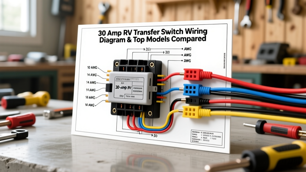
While specific pinouts vary slightly by manufacturer, the universal 30 amp RV transfer switch wiring diagram follows a strict three-wire 120V AC topology. The ATS essentially acts as a double-pole, double-throw (DPDT) relay system managing the Hot (L1) and Neutral (N) lines, while the Ground (G) is typically bonded directly through a continuous bus bar.
Terminal Block Routing and Pinout Configuration
- SHORE IN (L1, N, G): Receives 120V from the 30-amp shore power cord. Black to L1, White to N, Green to G.
- GEN IN (L1, N, G): Receives 120V from the onboard generator. Black to L1, White to N, Green to G.
- PANEL OUT (L1, N, G): Feeds the RV's main AC distribution panel. Black to L1, White to N, Green to G.
Expert Note: According to NFPA 70 (National Electrical Code) Article 551, the neutral and ground must NEVER be bonded inside the transfer switch or the main panel when connected to shore power. The ATS must switch both the Hot and Neutral lines simultaneously to ensure the RV's neutral remains isolated from the campground's neutral when on generator power.
Wire Gauge, Color Codes, and Torque Specifications
Improper wire termination is the leading cause of ATS meltdowns. Stranded wire must be properly prepared to prevent fraying and high-resistance connections. Refer to RVIA Electrical Standards for compliance on AC wiring terminations in recreational vehicles.
| Parameter | Specification | Technical Notes |
|---|---|---|
| Wire Size (AWG) | 10 AWG | Must be rated for 30A. THHN/THWN-2 or RV-rated stranded (UL 1426). |
| Hot Wire Color | Black | Line 1 (L1) - 120V AC |
| Neutral Wire Color | White | Must be switched by the ATS relay alongside the Hot wire. |
| Ground Wire Color | Green (or Bare) | Equipment Grounding Conductor. Passes through ATS ground bus. |
| Insulation Strip Length | 1/2 inch (12.7mm) | Do not over-strip; exposed copper outside the terminal is a shock hazard. |
| Terminal Torque | 14 in-lbs (1.58 Nm) | Use a calibrated inch-pound torque screwdriver. Do NOT guess. |
| Termination Method | Crimp Ferrules or Spades | Never insert bare stranded wire directly into screw-clamp terminals. |
Step-by-Step Installation and Termination Guide
- Isolate All Power Sources: Disconnect the shore power cord from the pedestal. Disconnect the negative terminal on the generator's 12V starter battery to prevent accidental cranking. Turn off the main breaker in the RV's AC distribution panel.
- Mount the ATS Enclosure: Secure the transfer switch to the RV subfloor or interior partition using #8 stainless steel wood screws. Ensure the knockouts are facing the incoming wire routes to avoid sharp bending radii on the 10 AWG cables.
- Prepare the 10 AWG Cables: Strip exactly 1/2 inch of insulation from the Black, White, and Green wires. Crimp an insulated 10 AWG fork terminal onto each wire using a heavy-duty ratcheting crimper. This prevents the screw terminal from severing individual copper strands.
- Route and Terminate: Feed the Shore, Generator, and Panel cables through separate knockouts. Connect the Green ground wires to the ATS ground bus bar. Connect the Black and White wires to their respective L1 and N terminal blocks as dictated by the manufacturer's 30 amp RV transfer switch wiring diagram.
- Apply Precision Torque: Using an inch-pound torque screwdriver set to 14 in-lbs, tighten all terminal screws. Give each wire a firm tug to verify mechanical retention.
- Test the Time-Delay Sequence: Reconnect shore power. Verify 120V at the main panel. Start the generator. Use a multimeter to monitor the 'PANEL OUT' terminals. You should see shore power drop out, followed by a 30-second dead period, before generator power engages at ~120V.
Troubleshooting Common Transfer Switch Failures
When an ATS fails, it usually manifests as a loss of power to the RV's main panel or a loud, continuous buzzing from the enclosure. Use this diagnostic tree to isolate the fault.
Symptom: Shore Power Works, but Generator Does Not Transfer
- Cause 1: Low Generator Output Voltage. Most ATS control boards feature a low-voltage lockout. If the generator's Automatic Voltage Regulator (AVR) is failing and outputting less than 104V, the ATS will refuse to engage the solenoid to protect your RV appliances.
- Fix 1: Measure the voltage at the 'GEN IN' L1 and N terminals while the generator is running. If it reads below 104V, the issue is the generator, not the ATS. If it reads 120V, check the 3-amp glass fuse located on the ATS control board.
Symptom: Loud Buzzing or Humming from the ATS Enclosure
- Cause 2: Incomplete Solenoid Pull-In. The internal relay requires full voltage to pull the heavy contactor shut. If the neutral terminal is loose, the control board experiences a voltage drop, causing the solenoid to rapidly chatter or hum without fully engaging.
- Fix 2: Immediately cut power. Inspect the White (Neutral) wires at both the 'GEN IN' and 'SHORE IN' terminal blocks. Look for heat discoloration or melted insulation. Re-crimp the wires and retorque to exactly 14 in-lbs.
Symptom: AC Breaker Trips Immediately Upon ATS Transfer
- Cause 3: Neutral-to-Ground Bonding Fault. If the RV's main panel has a neutral-to-ground bonding strap installed, and the generator also has a bonded neutral, the ATS switching sequence can create a parallel neutral path, triggering a Ground Fault Circuit Interrupter (GFCI) or tripping the main breaker due to circulating currents.
- Fix 3: Verify that the neutral and ground are isolated in the RV's main distribution panel. Per SAE and RVIA guidelines, the RV main panel must remain a sub-panel configuration (floating neutral) when fed by an ATS.
Mastering the 30 amp RV transfer switch wiring diagram is about more than just connecting black to black and white to white. It requires an understanding of relay logic, strict adherence to torque specifications, and a commitment to isolating neutral pathways. By selecting the right priority logic for your camping style and terminating your 10 AWG cables with precision, you ensure your RV's electrical system remains safe, reliable, and code-compliant for years to come.